Tool Post
The Model G4015Z comes supplied with a 4 way turret tool post. It is designed to accept up to 4- 1⁄2" tool bits. Other devices and holders may be installed into the tool post and arranged as in Figure 9. When more than one tool is secured into the tool post, changing from one tool to another is quickly done by loosening the lock lever (#5) and rotating the post to the desired tool. A
If using tool bits that require shimming, be sure to use steel shims as opposed to aluminum or brass shims. Soft shims may give, allowing the tool bit to become loose!
When securing a tool bit into the tool post, always remember these rules:
•Secure the tool bit with at least 2 bolts on the tool post.
•Make sure the top of the tool bit is at the lathe spindle center line or just below. The tailstock center can be used as in Figure 10.
•Never extend the tool bit more than 21⁄2 times its thickness from the edge of the tool rest. i.e. a 3⁄8" tool bit should only extend 15⁄16" past the bot- tom of the tool rest. Less is best!
•Always use sharp tool bits.
1
5
4
2
3
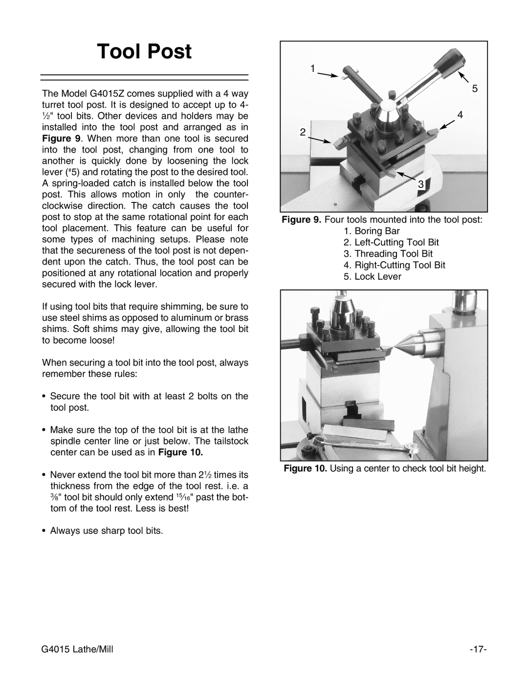
Figure 9. Four tools mounted into the tool post:
1.Boring Bar
2.Left-Cutting Tool Bit
3.Threading Tool Bit
4.Right-Cutting Tool Bit
5.Lock Lever
Figure 10. Using a center to check tool bit height.
G4015 Lathe/Mill |