HEATER INSTALLATION
Fan and Heater
Air Pressure Switch and
Temperature Sensor Box
Installation
1.Using air switch box as a guide, mark 2 holes on ple- num side wall appproximately 24" to right of transition cen- tered up and down in plenum.
2.Drill air switch filter hole 5/8" diameter for snug fit. Drill tem- perature sensor hole 5/8" or
larger to accommodate mounting nut.
3.Mount Box to Bin using (4) self drilling screws
4.Caulk between housing and side- wall to seal.
Air Switch Box Assembly
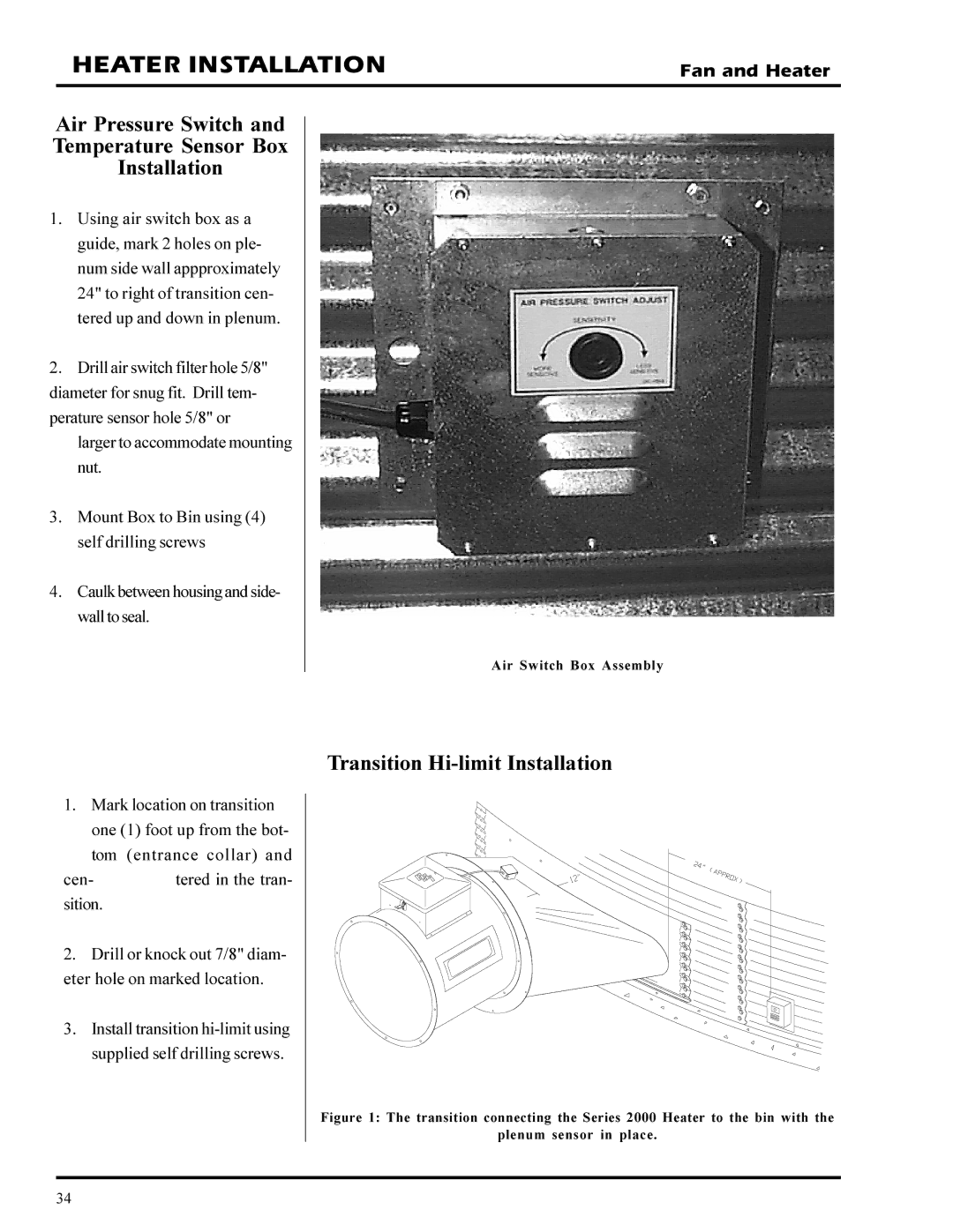
1.Mark location on transition one (1) foot up from the bot-
tom (entrance collar) and
cen- tered in the tran- sition.
2.Drill or knock out 7/8" diam- eter hole on marked location.
3.Install transition
Transition Hi-limit Installation
Figure 1: The transition connecting the Series 2000 Heater to the bin with the
plenum sensor in place.
34