For Vertical Runs
The flue system must be supported every eight (8) feet (2.4 M) above the heater flue outlet by wall brackets.
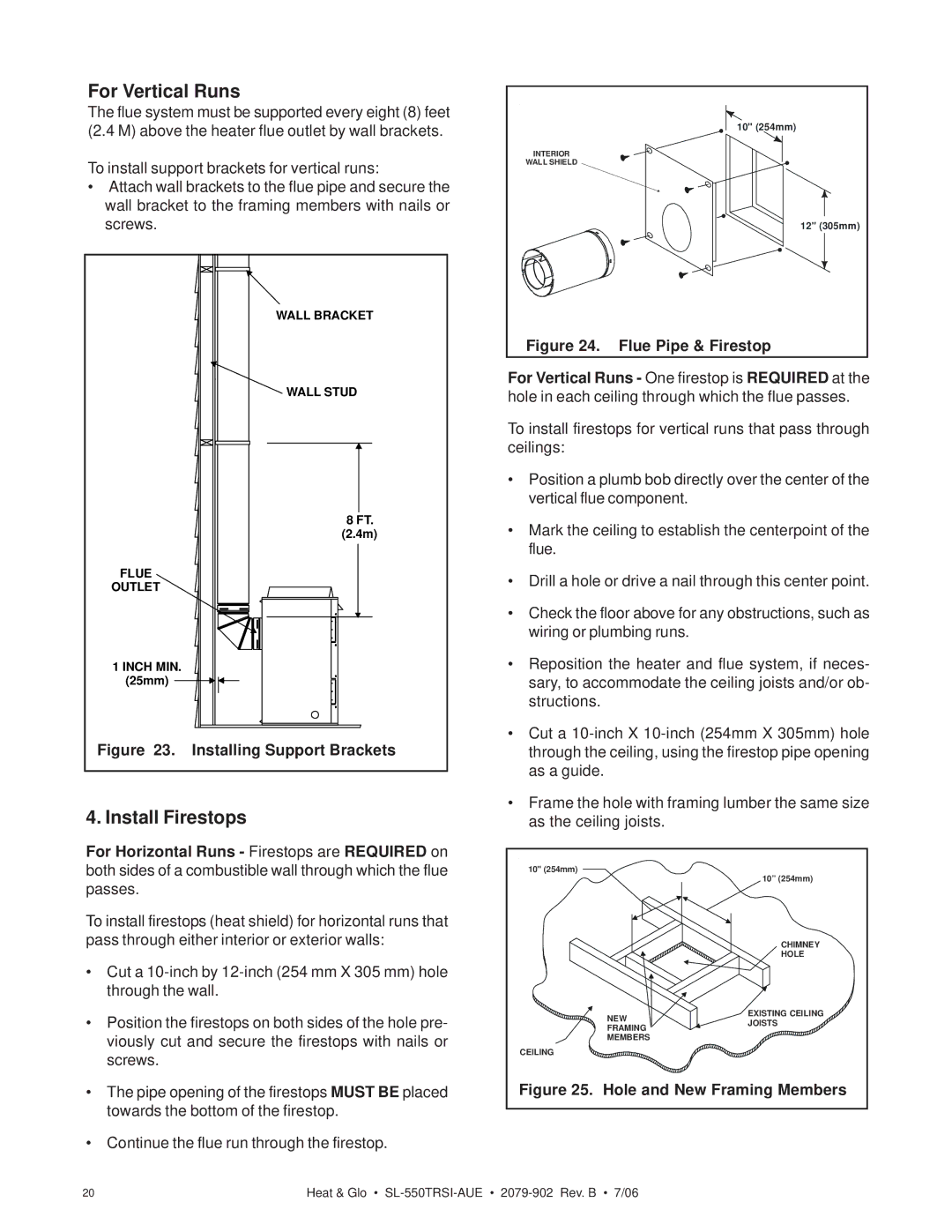
To install support brackets for vertical runs:
• Attach wall brackets to the flue pipe and secure the wall bracket to the framing members with nails or screws.
WALL BRACKET
![]() WALL STUD
WALL STUD
8 FT.
(2.4m)
FLUE
OUTLET
1 INCH MIN.
(25mm) ![]()
![]()
Figure 23. Installing Support Brackets
4. Install Firestops
For Horizontal Runs - Firestops are REQUIRED on both sides of a combustible wall through which the flue passes.
To install firestops (heat shield) for horizontal runs that pass through either interior or exterior walls:
•Cut a
•Position the firestops on both sides of the hole pre- viously cut and secure the firestops with nails or screws.
•The pipe opening of the firestops MUST BE placed towards the bottom of the firestop.
•Continue the flue run through the firestop.
| 10" (254mm) |
INTERIOR |
|
WALL SHIELD |
|
| 12" (305mm) |
Figure 24. | Flue Pipe & Firestop |
For Vertical Runs - One firestop is REQUIRED at the hole in each ceiling through which the flue passes.
To install firestops for vertical runs that pass through ceilings:
•Position a plumb bob directly over the center of the vertical flue component.
•Mark the ceiling to establish the centerpoint of the flue.
•Drill a hole or drive a nail through this center point.
•Check the floor above for any obstructions, such as wiring or plumbing runs.
•Reposition the heater and flue system, if neces- sary, to accommodate the ceiling joists and/or ob- structions.
•Cut a
•Frame the hole with framing lumber the same size as the ceiling joists.
10" (254mm) |
| 10” (254mm) |
|
| |
|
| CHIMNEY |
|
| HOLE |
| NEW | EXISTING CEILING |
| JOISTS | |
| FRAMING | |
| MEMBERS |
|
CEILING |
|
|
Figure 25. Hole and New Framing Members | ||
20 | Heat & Glo • |