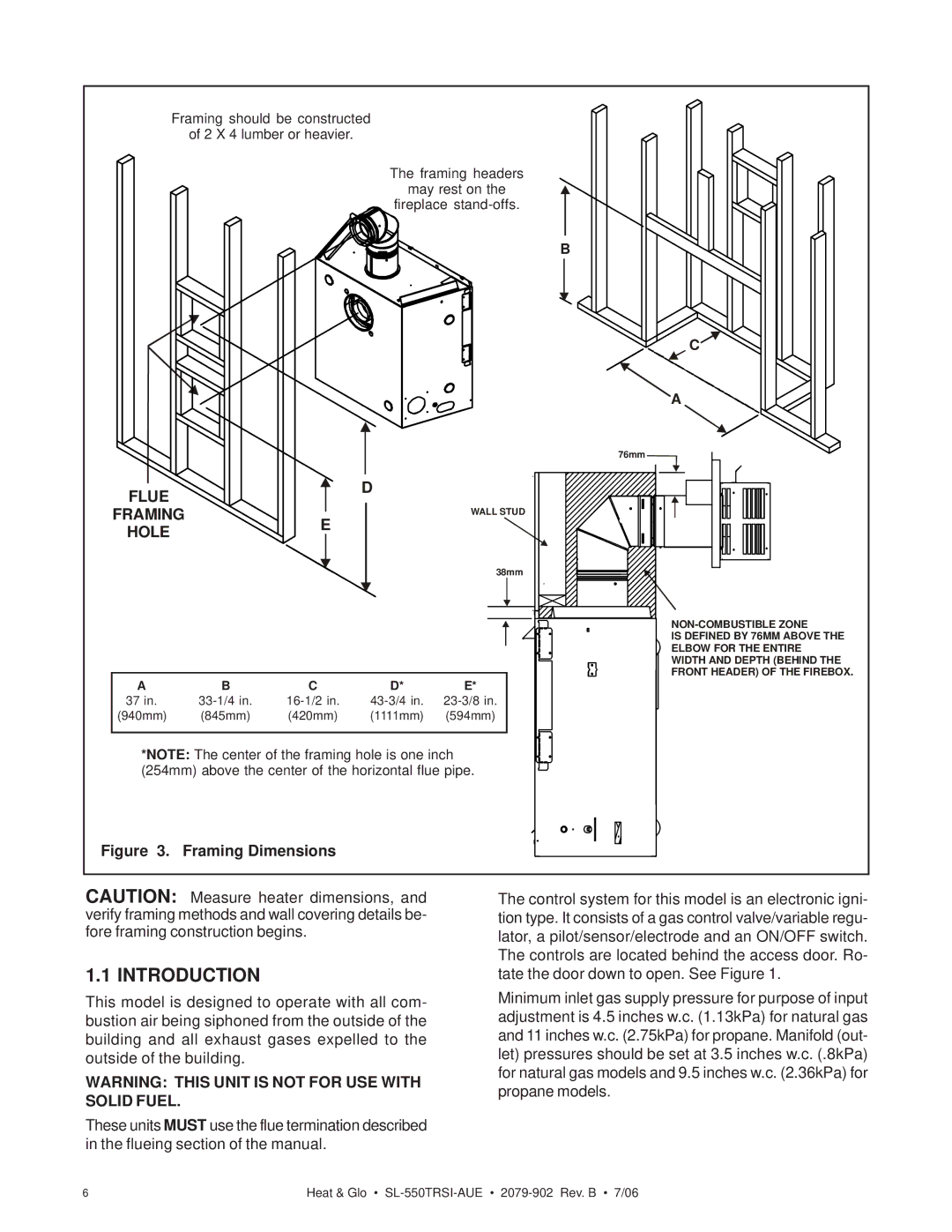
Framing should be constructed
of 2 X 4 lumber or heavier.
The framing headers
may rest on the
fireplace
B
FLUE |
| D |
|
| |
FRAMING | E | WALL STUD |
| ||
HOLE |
| |
|
| |
|
| 38mm |
A | B | C | D* | E* |
37 in. | ||||
(940mm) | (845mm) | (420mm) | (1111mm) | (594mm) |
|
|
|
|
|
*NOTE: The center of the framing hole is one inch (254mm) above the center of the horizontal flue pipe.
C![]()
![]() A
A
76mm![]()
IS DEFINED BY 76MM ABOVE THE ELBOW FOR THE ENTIRE WIDTH AND DEPTH (BEHIND THE FRONT HEADER) OF THE FIREBOX.
Figure 3. Framing Dimensions
CAUTION: Measure heater dimensions, and verify framing methods and wall covering details be- fore framing construction begins.
1.1 INTRODUCTION
This model is designed to operate with all com- bustion air being siphoned from the outside of the building and all exhaust gases expelled to the outside of the building.
WARNING: THIS UNIT IS NOT FOR USE WITH SOLID FUEL.
These units MUST use the flue termination described in the flueing section of the manual.
The control system for this model is an electronic igni- tion type. It consists of a gas control valve/variable regu- lator, a pilot/sensor/electrode and an ON/OFF switch. The controls are located behind the access door. Ro- tate the door down to open. See Figure 1.
Minimum inlet gas supply pressure for purpose of input adjustment is 4.5 inches w.c. (1.13kPa) for natural gas and 11 inches w.c. (2.75kPa) for propane. Manifold (out- let) pressures should be set at 3.5 inches w.c. (.8kPa) for natural gas models and 9.5 inches w.c. (2.36kPa) for propane models.
6 | Heat & Glo • |