Installing the Trim
Combustible materials may be brought up to the specified clearances on the side and top front edges of the fireplace, but MUST NEVER overlap onto the front face. The joints between the finished wall and the fireplace top and sides can only be sealed with a 300° F. (149° C) minimum sealant.
!WARNING: WHEN FINISHING THE FIRE- PLACE, NEVER OBSTRUCT OR MODIFY THE AIR INLET/OUTLET GRILLES IN ANY MANNER.
Install optional marble and brass trim surround kits as desired. Marble, brass, brick, tile, or other non- combustible materials can be used to cover up the gap between the sheet rock and the fireplace.
Do not obstruct or modify the air inlet/outlet grilles. When overlapping on both sides, leave enough space so that the bottom grille can be opened and the trim door removed.
1.7INSTALLER TESTING
The space heater must be tested and be operating ac- cording to manufacturer's specifications prior to the in- staller leaving the site. Note: the tips of the flames should never hit the top of the firebox after the unit has warmed up. Please contact your dealer or a qualified service person to replace injector or adjust valve.
Upon completing the gas line connection, a small amount of air will be in the lines. When first lighting the pilot light, it will take a few minutes for the lines to purge themselves of this air. Once the purging is com- plete, the pilot and burner will light and operate as indi- cated in the Lighting Instructions.
Subsequent lightings of the appliance will not require such purging.
Follow the Safety Information and Lighting Instructions pages of this manual to light the appliance.
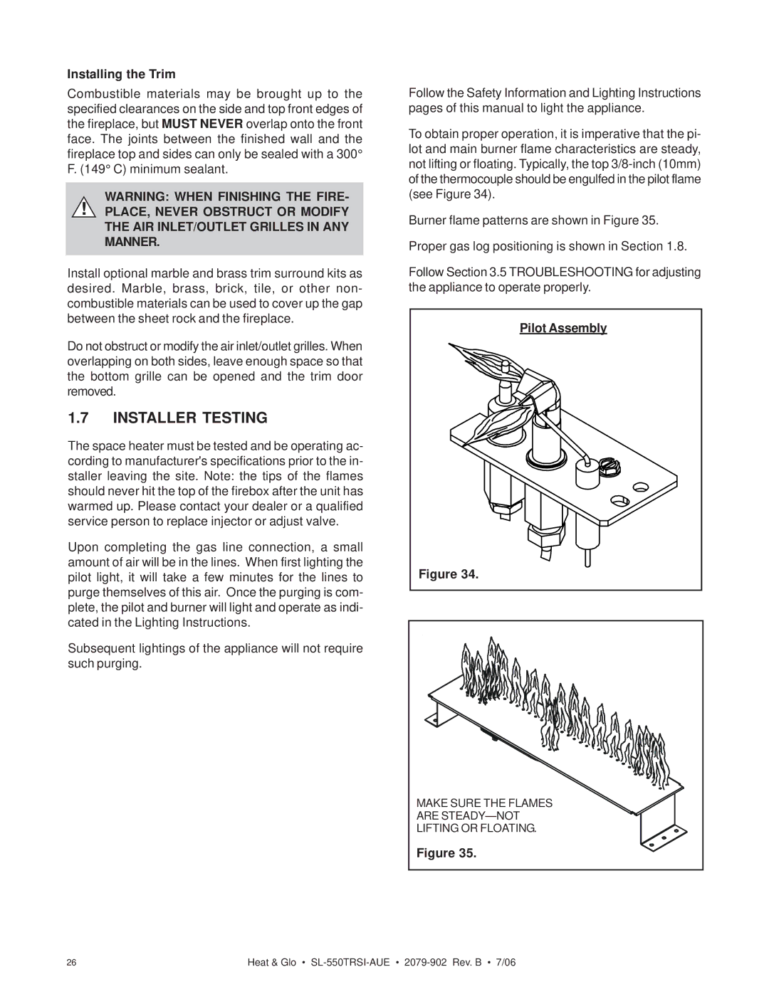
To obtain proper operation, it is imperative that the pi- lot and main burner flame characteristics are steady, not lifting or floating. Typically, the top
Burner flame patterns are shown in Figure 35. Proper gas log positioning is shown in Section 1.8.
Follow Section 3.5 TROUBLESHOOTING for adjusting the appliance to operate properly.
Pilot Assembly
Figure 34.
MAKE SURE THE FLAMES
ARE
LIFTING OR FLOATING.
Figure 35.
26 | Heat & Glo • |