3.1REMOVAL OF COVERS FOR SERVICING
A. Control Compartment Door
•Rotate the lower door down to access the gas controls. B. Dress Guard and Glass Door
•Lift the front dress guard up and out away from the appliance side surrounds. Replace the dress guard when servicing is complete.
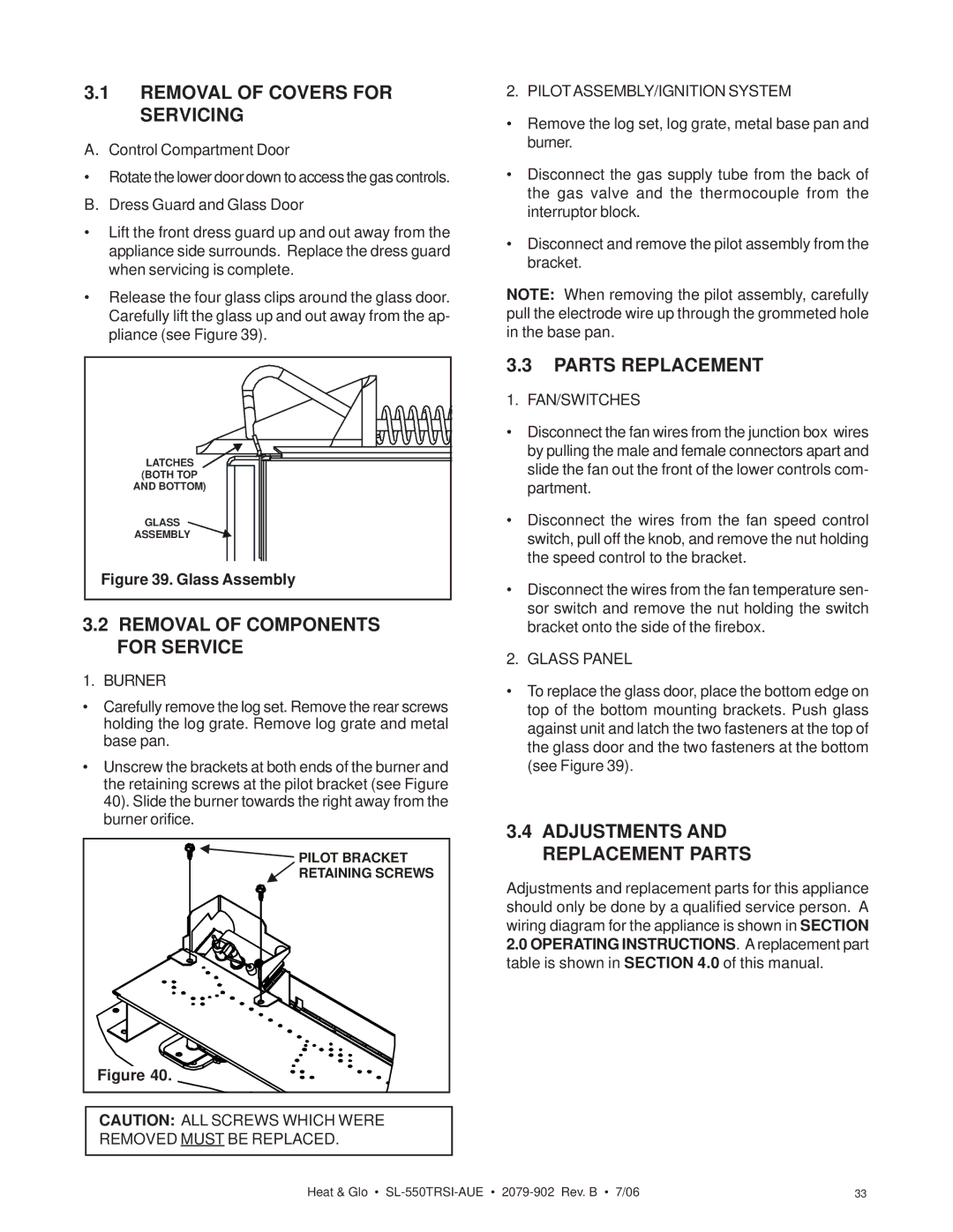
•Release the four glass clips around the glass door. Carefully lift the glass up and out away from the ap- pliance (see Figure 39).
LATCHES |
(BOTH TOP |
AND BOTTOM) |
GLASS |
ASSEMBLY |
Figure 39. Glass Assembly |
3.2REMOVAL OF COMPONENTS FOR SERVICE
1. BURNER
•Carefully remove the log set. Remove the rear screws holding the log grate. Remove log grate and metal base pan.
•Unscrew the brackets at both ends of the burner and the retaining screws at the pilot bracket (see Figure 40). Slide the burner towards the right away from the burner orifice.
PILOT BRACKET |
RETAINING SCREWS |
Figure 40. |
CAUTION: ALL SCREWS WHICH WERE REMOVED MUST BE REPLACED.
2. PILOTASSEMBLY/IGNITION SYSTEM
•Remove the log set, log grate, metal base pan and burner.
•Disconnect the gas supply tube from the back of the gas valve and the thermocouple from the interruptor block.
•Disconnect and remove the pilot assembly from the bracket.
NOTE: When removing the pilot assembly, carefully pull the electrode wire up through the grommeted hole in the base pan.
3.3PARTS REPLACEMENT
1. FAN/SWITCHES
•Disconnect the fan wires from the junction box wires by pulling the male and female connectors apart and slide the fan out the front of the lower controls com- partment.
•Disconnect the wires from the fan speed control switch, pull off the knob, and remove the nut holding the speed control to the bracket.
•Disconnect the wires from the fan temperature sen- sor switch and remove the nut holding the switch bracket onto the side of the firebox.
2. GLASS PANEL
•To replace the glass door, place the bottom edge on top of the bottom mounting brackets. Push glass against unit and latch the two fasteners at the top of the glass door and the two fasteners at the bottom (see Figure 39).
3.4ADJUSTMENTS AND REPLACEMENT PARTS
Adjustments and replacement parts for this appliance should only be done by a qualified service person. A wiring diagram for the appliance is shown in SECTION 2.0 OPERATING INSTRUCTIONS. A replacement part table is shown in SECTION 4.0 of this manual.
Heat & Glo • | 33 |