FLAME SPARKER/ | |
SENSOR | VALVE |
| REMOTE |
| CONTROL |
| ANT. |
| ON/OFF |
PILOT | WALL SWITCH |
| IGNITION |
IGNITION MODULE | MODULE |
6VDC | (6V) |
| |
| GROUND |
NEUTRAL | HOT |
BATTERY PORT |
|
| PLUG IN |
ON/OFF | THERMOCOUPLE |
BLOCK | |
SWITCH | (CONNECTED TO |
| BACK OF VALVE) |
| VALVE |
GAS LINE |
|
CONNECTED TO |
|
BACK OF VALVE |
|
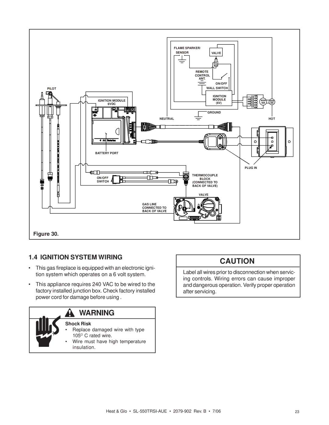
Figure 30. |
|
1.4 IGNITION SYSTEM WIRING
•This gas fireplace is equipped with an electronic igni- tion system which operates on a 6 volt system.
•This appliance requires 240 VAC to be wired to the factory installed junction box. Check factory installed power cord for damage before using .
CAUTION
Label all wires prior to disconnection when servic- ing controls. Wiring errors can cause improper and dangerous operation. Verify proper operation after servicing.
WARNING
Shock Risk
• Replace damaged wire with type 105O C rated wire.
• Wire must have high temperature insulation.
Heat & Glo • | 23 |