TABLE 1
MODEL | FLUE TERMINATION APPROVALS | |
| ||
|
|
1.2 FLUE SYSTEM APPROVALS
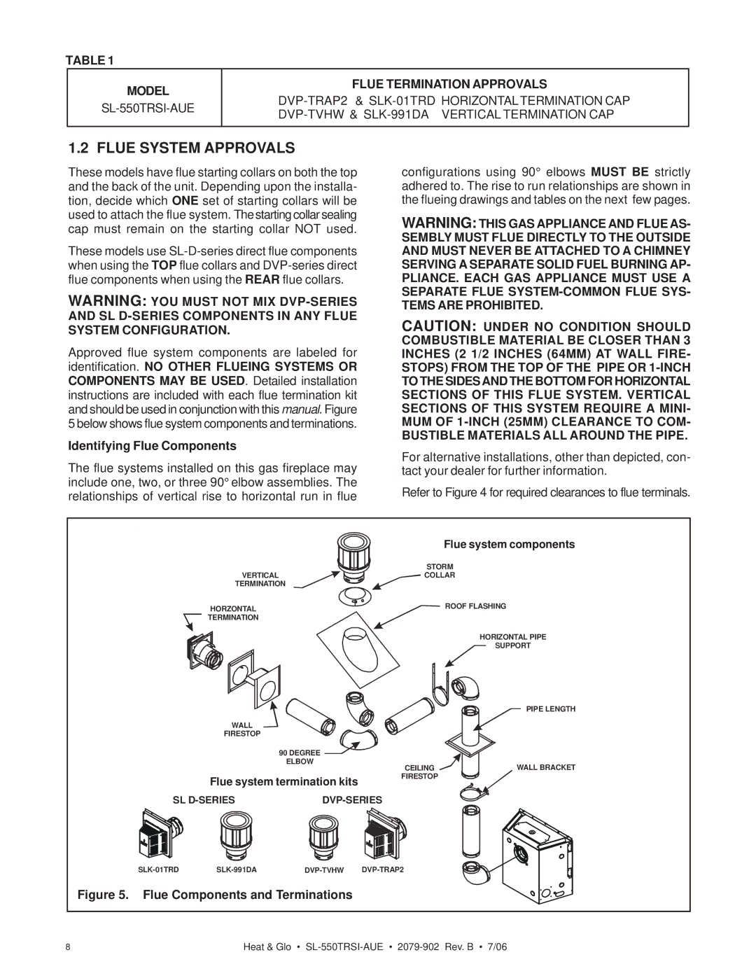
These models have flue starting collars on both the top and the back of the unit. Depending upon the installa- tion, decide which ONE set of starting collars will be used to attach the flue system. The starting collar sealing cap must remain on the starting collar NOT used.
These models use
WARNING: YOU MUST NOT MIX
Approved flue system components are labeled for identification. NO OTHER FLUEING SYSTEMS OR COMPONENTS MAY BE USED. Detailed installation instructions are included with each flue termination kit and should be used in conjunction with this manual. Figure 5 below shows flue system components and terminations.
Identifying Flue Components
The flue systems installed on this gas fireplace may include one, two, or three 90° elbow assemblies. The relationships of vertical rise to horizontal run in flue
configurations using 90° elbows MUST BE strictly adhered to. The rise to run relationships are shown in the flueing drawings and tables on the next few pages.
WARNING: THIS GAS APPLIANCE AND FLUE AS- SEMBLY MUST FLUE DIRECTLY TO THE OUTSIDE AND MUST NEVER BE ATTACHED TO A CHIMNEY SERVING A SEPARATE SOLID FUEL BURNING AP- PLIANCE. EACH GAS APPLIANCE MUST USE A SEPARATE FLUE
CAUTION: UNDER NO CONDITION SHOULD COMBUSTIBLE MATERIAL BE CLOSER THAN 3 INCHES (2 1/2 INCHES (64MM) AT WALL FIRE-
STOPS) FROM THE TOP OF THE PIPE OR
BUSTIBLE MATERIALS ALL AROUND THE PIPE. For alternative installations, other than depicted, con- tact your dealer for further information.
Refer to Figure 4 for required clearances to flue terminals.
|
|
|
| Flue system components |
|
|
| STORM | |
| VERTICAL |
| COLLAR | |
| TERMINATION |
|
| |
| HORZONTAL |
|
| ROOF FLASHING |
| TERMINATION |
|
|
|
|
|
|
| HORIZONTAL PIPE |
|
|
|
| SUPPORT |
|
|
|
| PIPE LENGTH |
| WALL |
|
|
|
| FIRESTOP |
|
|
|
|
| 90 DEGREE |
|
|
|
| ELBOW | CEILING | WALL BRACKET |
|
|
| ||
| Flue system termination kits | FIRESTOP |
| |
|
|
| ||
SL |
|
|
| |
| ||||
Figure 5. Flue Components and Terminations |
|
| ||
8 | Heat & Glo • | |||