Manuals
/
Heat Controller
/
Household Appliance
/
Heat Pump
Heat Controller
VMH24SC-1
service manual
VMH09SC-1 A-VMH12SC-1 VMH18SC-1
Models:
VMH18SC-1
VMH09SC-1
VMH24SC-1
VMH12SC-1
1
14
45
45
Download
45 pages
50.02 Kb
11
12
13
14
15
16
17
18
Troubleshooting
Operation characteristics
Install
Refrigerant Cycle Diagram
Indoor Unit Error Display
Outdoor unit Compressor delay
Dimension
Ionizer Clean Air function
Preheat mode
Page 14
Image 14
Service Manual
VMH Series
Heat Controller, Inc.
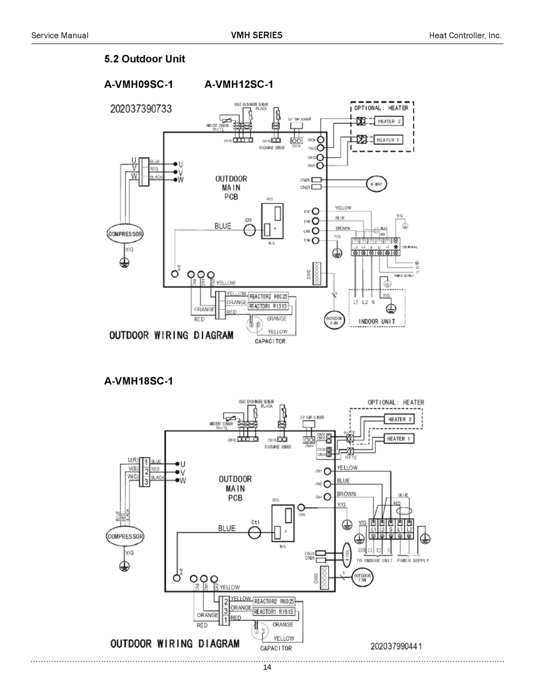
5.2 Outdoor Unit
A-VMH09SC-1
A-VMH12SC-1
A-VMH18SC-1
14
Page 13
Page 15
Page 14
Image 14
Page 13
Page 15
Contents
Inverter Single Zone Ductless Mini Split Heat Pump
Contents
Installation
Precaution
Safety Precaution
For installation, always contact the dealer
Caution
Use two or more people to lift and transport the product
Keep level even when installing the product
Operational
Do not block the inlet or outlet of air flow
Do not drink the water drained from the product
Function
Anti-freeze protection in cooling
Outdoor unit Compressor delay
Dimension
Indoor Unit
Model Dimension mm
Outdoor Unit
Refrigerant Cycle Diagram
Indoor Outdoor
Wiring Diagrams
VMH09SC-1 A-VMH12SC-1 VMH18SC-1
Installation details
Pipe length and the elevation
Single Zone V Series Inverter System
Pressure Test & Evacuation
System Evacuation and Charging
Operation characteristics
Display function
Electronic function
Abbreviation
Main Protection
Operation Modes and Functions
Preheat mode
Fan only mode
Preheat termination
Cooling Mode Compressor running rules
Frequency decreases Holds
Model Current
Indoor fan running rules
Condenser high temperature T3 protection
Outdoor fan rules
Evaporator low temperature T2 protection
Heating Mode Compressor running rules
T1-Ts-ΔT +5.0 +4.5 +3.5 +3.0 +2.5 +2.0 +1.5 +1.0 +0.5
I1HEAT I2HEAT I3HEAT
Outdoor fan running rules
VMH12SC-1
Indoor fan rules
Unit TEL0 TEL1 VMH09SC-1
VMH18SC-1
Defrost mode:
Defrost Actions For 9K and 12K unit For 18K and 24K unit
High evaporator coil temp.T2 protection
Auto-mode
Dehumidify mode
Forced operation function
Timer function
Sleep function mode
Automatic front panel function
Ionizer Clean Air function
Auto-Restart function
Troubleshooting
Safety
Eeprom parameter error diagnosis and solution
Indoor Unit Error Display
Diagnosis and Solution
VMH Series
E3 Indoor or E7 Outdoor
Igbt over current protection diagnosis and solution
VMH Series
29 P3 Error Low Ambient Protection
Inverter compressor drive error diagnosis and solution
Key parts checking
Position Resistance Value
VMH Series
Some frequently-used R-T data for T1, T2, T3 and T4 sensor
2012
Top
Page
Image
Contents