Heat Controller, Inc.
VMH Series
Service Manual
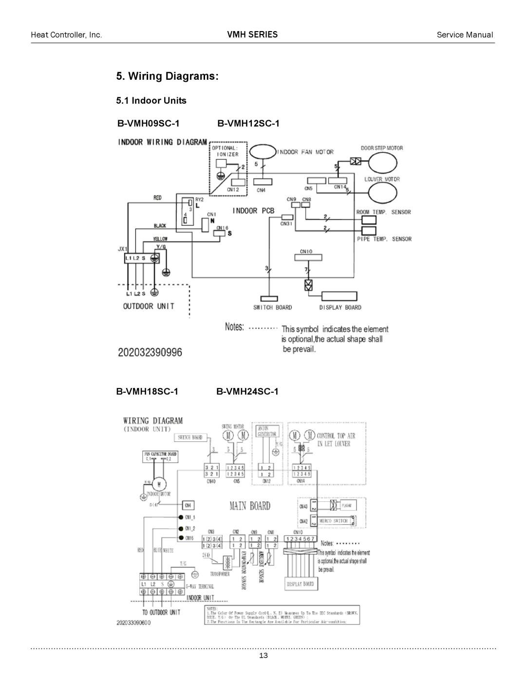
5.1 Indoor Units
B-VMH09SC-1 B-VMH12SC-1
B-VMH18SC-1 B-VMH24SC-1
13