C

V

J

B


B


V

B


V


D


V


V

A

F

G

M

V

H or i

X V H

V H V

E

V

A

O

N

P

R

Q


V


L


K


K


Electrical


V


V


V= VENT TERMINAL X = AIR SUPPLY INLET

= AREA WHERE TERMINAL IS NOT PERMITTED

A

=

12 inches

clearances above grade, veranda,


porch, deck or balcony

B

=

12 inches

clearance to window or door that may


be opened, or to permanently closed


window

C

=

18 inches

clearance below unventilated soffit


18 inches

clearance below ventilated soffit


30 inches

clearance below vinyl soffits and


electrical service

D

=

6 inches

clearance to outside corner

E

=

6 inches

clearance to inside corner

F

=

3 ft. (Canada)

not to be installed above a gas me-


ter/regulator assembly within 3 feet


horizontally from the center-line of the


regulator

G

=

3 ft

clearance to gas service regulator


vent outlet

H

=

12 inches

clearance to non-mechanical (unpow-


ered) air supply inlet, combustion air

i

=

3 ft. (U.S.A.)

inlet or direct-vent termination


6 ft. (Canada)

clearance to a mechanical (powered)


air supply inlet

All mechanical air intakes within 10 feet of a termination cap must be a minimum of 3 feet below termination.

J

= 7 ft

On public property: clearance above


paved sidewalk or a paved driveway.

A vent shall not terminate directly above a sidewalk or paved driveway which is located between two single family dwellings and serves both dwellings.

K

=

6 inches

clearance from sides of electrical


service

L

=

12 inches

clearance above electrical service

Location of the vent termination must not interfere with access to the electrical service.

M = 18 inches

clearanceunderveranda,porch,deck,


balcony or overhang

42 inches

vinyl or composite overhang

Permitted when veranda, porch, deck or balcony is fully open on a minimum of 2 sides beneath the floor.

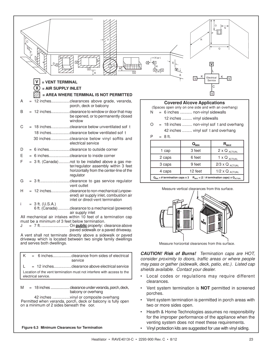
Figure 6.3 Minimum Clearances for Termination

Service

C

V

Covered Alcove Applications

(Spaces open only on one side and with an overhang)

N= 6 inches ........... non-vinyl sidewalls 12 inches ......... vinyl sidewalls

O= 18 inches ......... non-vinyl soffit and overhang 42 inches ......... vinyl soffit and overhang

P= 8 ft.


QMIN

RMAX

1 cap

3 feet

2 x Q ACTUAL

2 caps

6 feet

1 x Q ACTUAL

3 caps

9 feet

2/3 x Q ACTUAL

4 caps

12 feet

1/2 x Q ACTUAL

QMIN = # termination caps x 3 RMAX = (2 / # termination caps) x QACTUAL

Measure vertical clearances from this surface.

Measure horizontal clearances from this surface.

CAUTION! Risk of Burns! Termination caps are HOT, consider proximity to doors, traffic areas or where people may pass or gather (sidewalk, deck, patio, etc.). Listed cap shields available. Contact your dealer.

Local codes or regulations may require different clearances.

Vent system termination is NOT permitted in screened porches.

Vent system termination is permitted in porch areas with two or more sides open.

Hearth & Home Technologies assumes no responsibility for the improper performance of the appliance when the venting system does not meet these requirements.

Vinyl protection kits are suggested for use with vinyl siding.

Heatilator • RAVE4013I-C2293-900 Rev. C • 8/12

23

Page 23
Image 23
Heatiator Rave4013i-c owner manual Covered Alcove Applications, Minimum Clearances for Termination

Rave4013i-c specifications

The Heatiator Rave4013i-c stands out as an exceptional heating solution designed to provide efficient, reliable warmth while elevating the aesthetic appeal of any space. This advanced model offers a blend of innovative technology, high performance, and user-friendly features.

One of the most notable characteristics of the Rave4013i-c is its cutting-edge air distribution system. This ensures uniform heat distribution throughout the room, eliminating cold spots and providing consistent warmth. The unit's powerful heat output makes it suitable for various environments, including residential homes, offices, and commercial spaces.

The Rave4013i-c is equipped with energy-efficient technologies that reduce power consumption while maintaining optimal performance. With an impressive heating capacity, the unit is designed to heat larger spaces effectively without incurring steep energy costs. Users appreciate its eco-friendly design, which aligns with today's sustainability goals, helping to lower carbon footprints.

Another significant feature is the sophisticated digital control panel, which allows users to customize their heating experience. The intuitive interface provides easy access to various settings, including temperature adjustments, timer functions, and mode selection. This level of control ensures that users can achieve their desired comfort level with minimal hassle.

The Heatiator Rave4013i-c also boasts an aesthetically pleasing design, incorporating sleek lines and a modern finish that complements any decor. The charming appearance does not compromise its robustness; it is built from high-quality materials that promise durability and long-lasting performance.

Safety is a top priority for the Rave4013i-c. It includes essential safety features such as overheat protection and tip-over switches. These integrated safety measures provide peace of mind, especially in homes with pets and small children. Additionally, its low noise operation allows for peaceful enjoyment of the warmth generated, without disruptive sounds.

Versatility is another hallmark of the Rave4013i-c. It can be installed in various configurations, whether flush-mounted in a wall or standing independently, making it adaptable to different room layouts. This flexibility, combined with its heating efficiency and modern design, makes the Heatiator Rave4013i-c an ideal choice for anyone seeking a high-quality heating appliance that enhances both comfort and style.