Rave4013i-c specifications
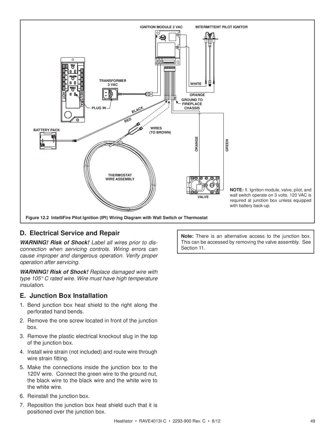
The Heatiator Rave4013i-c stands out as an exceptional heating solution designed to provide efficient, reliable warmth while elevating the aesthetic appeal of any space. This advanced model offers a blend of innovative technology, high performance, and user-friendly features.One of the most notable characteristics of the Rave4013i-c is its cutting-edge air distribution system. This ensures uniform heat distribution throughout the room, eliminating cold spots and providing consistent warmth. The unit's powerful heat output makes it suitable for various environments, including residential homes, offices, and commercial spaces.
The Rave4013i-c is equipped with energy-efficient technologies that reduce power consumption while maintaining optimal performance. With an impressive heating capacity, the unit is designed to heat larger spaces effectively without incurring steep energy costs. Users appreciate its eco-friendly design, which aligns with today's sustainability goals, helping to lower carbon footprints.
Another significant feature is the sophisticated digital control panel, which allows users to customize their heating experience. The intuitive interface provides easy access to various settings, including temperature adjustments, timer functions, and mode selection. This level of control ensures that users can achieve their desired comfort level with minimal hassle.
The Heatiator Rave4013i-c also boasts an aesthetically pleasing design, incorporating sleek lines and a modern finish that complements any decor. The charming appearance does not compromise its robustness; it is built from high-quality materials that promise durability and long-lasting performance.
Safety is a top priority for the Rave4013i-c. It includes essential safety features such as overheat protection and tip-over switches. These integrated safety measures provide peace of mind, especially in homes with pets and small children. Additionally, its low noise operation allows for peaceful enjoyment of the warmth generated, without disruptive sounds.
Versatility is another hallmark of the Rave4013i-c. It can be installed in various configurations, whether flush-mounted in a wall or standing independently, making it adaptable to different room layouts. This flexibility, combined with its heating efficiency and modern design, makes the Heatiator Rave4013i-c an ideal choice for anyone seeking a high-quality heating appliance that enhances both comfort and style.

