. A complete Parts List is available at www.HobartWelders.com
6-3. Typical Stick Welding Connections And Control Settings
! Stop engine.
|
|
|
|
|
|
|
|
|
|
|
|
| . This section provides general | ||
|
|
|
|
|
|
|
|
|
|
|
|
|
| guidelines and may not suit all | |
|
|
|
|
|
|
|
|
|
|
|
|
|
| applications. | |
|
|
|
|
|
|
|
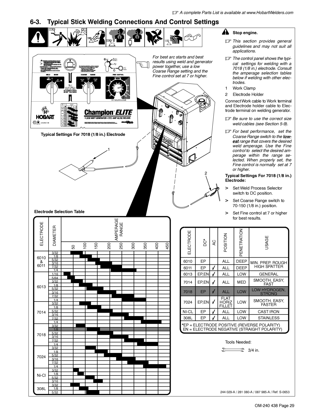
| For best arc starts and best |
| . The control panel shows the typi- | |||||
|
|
|
|
|
|
|
| results using weld and generator |
| cal settings for welding with a | |||||
|
|
|
|
|
|
|
| power together, use a low |
|
| |||||
|
|
|
|
|
|
|
|
|
| 7018 (1/8 in.) electrode. Consult | |||||
|
|
|
|
|
|
|
| Coarse Range setting and the |
|
| |||||
|
|
|
|
|
|
|
|
|
| the amperage selection tables | |||||
|
|
|
|
|
|
|
| Fine control set at 7 or higher. |
|
| |||||
|
|
|
|
|
|
|
|
|
| below if welding with other elec- | |||||
|
|
|
|
|
|
|
|
|
|
|
|
|
| ||
|
|
|
|
|
|
|
|
|
|
|
|
|
| trodes. |
|
|
|
|
|
|
|
|
|
|
|
|
|
| 1 | Work Clamp | |
|
|
|
|
|
|
|
|
|
|
|
|
| 2 | Electrode Holder | |
|
|
|
|
|
|
|
|
|
|
|
|
| Connect Work cable to Work terminal | ||
|
|
|
|
|
|
|
|
|
|
|
|
| and Electrode holder cable to Elec- | ||
|
|
|
|
|
|
|
|
|
|
|
|
| trode terminal on welding generator. | ||
|
|
|
|
|
|
|
|
|
|
|
|
| . Be sure to use the correct size | ||
|
|
|
|
|
|
|
|
|
|
|
|
|
| weld cables (see Section | |
Typical Settings For 7018 (1/8 in.) Electrode |
|
|
|
|
|
|
| . For best performance, set the | |||||||
|
|
|
|
|
|
|
| Coarse Range switch to the low- | |||||||
|
|
|
|
|
|
|
|
|
|
|
|
|
| ||
|
|
|
|
|
|
|
|
|
|
|
|
|
| est range that covers the desired | |
|
|
|
|
| 1 |
|
|
|
|
|
|
|
| weld amperage. Use the Fine | |
|
|
|
|
|
|
|
|
|
|
|
|
| control to | select the desired am- | |
|
|
|
|
|
|
|
|
|
|
|
|
|
| perage within the range se- | |
|
|
|
|
|
|
|
|
|
|
|
|
|
| lected. When properly set, the | |
|
|
|
|
|
|
|
|
|
|
|
|
|
| Fine control is normally set at 7 | |
|
|
|
|
|
|
|
|
|
|
| 2 |
|
| or higher. |
|
|
|
|
|
|
|
|
|
|
|
|
| Typical Settings For 7018 (1/8 in.) | |||
|
|
|
|
|
|
|
|
|
|
|
|
| |||
|
|
|
|
|
|
|
|
|
|
|
|
| Electrode: |
| |
|
|
|
|
|
|
|
|
|
|
|
|
| > Set Weld Process Selector | ||
|
|
|
|
|
|
|
|
|
|
|
|
|
| switch to DC position. | |
|
|
|
|
|
|
|
|
|
|
|
|
| > Set Coarse Range switch to | ||
|
|
|
|
|
|
|
|
|
|
|
|
|
| ||
Electrode Selection Table |
|
|
|
|
|
|
|
|
| > Set Fine control at 7 or higher | |||||
|
|
|
|
|
|
|
|
|
|
|
|
| |||
ELECTRODE |
|
| 100 | 150 | 200 AMPERAGE 250 RANGE | 300 | 350 | 400 | 450 | ELECTRODE | DC* |
| POSITION | for best results. | |
DIAMETER | 50 | AC | PENETRATION | USAGE | |||||||||||
| 3/32 |
|
|
|
|
|
|
|
|
|
|
|
|
|
|
6010 | 1/8 |
|
|
|
|
|
|
|
|
|
|
|
|
|
|
& | 5/32 |
|
|
|
|
|
|
|
| 6010 | EP |
| ALL | DEEP | MIN. PREP, ROUGH |
3/16 |
|
|
|
|
|
|
|
|
| ||||||
6011 | 7/32 |
|
|
|
|
|
|
|
| 6011 | EP |
| ALL | DEEP | HIGH SPATTER |
| 1/4 |
|
|
|
|
|
|
|
|
|
| ||||
|
|
|
|
|
|
|
|
| 6013 | EP,EN |
| ALL | LOW | GENERAL | |
| 1/16 |
|
|
|
|
|
|
|
|
| |||||
| 5/64 |
|
|
|
|
|
|
|
|
|
|
|
|
| SMOOTH, EASY, |
| 3/32 |
|
|
|
|
|
|
|
| 7014 | EP,EN |
| ALL | MED | |
|
|
|
|
|
|
|
|
|
| FAST | |||||
6013 | 1/8 |
|
|
|
|
|
|
|
|
|
|
|
|
| |
5/32 |
|
|
|
|
|
|
|
|
|
|
|
|
| LOW HYDROGEN, | |
|
|
|
|
|
|
|
|
| 7018 | EP |
| ALL | LOW | ||
| 3/16 |
|
|
|
|
|
|
|
|
| STRONG | ||||
| 7/32 |
|
|
|
|
|
|
|
|
|
|
| FLAT |
| |
|
|
|
|
|
|
|
|
|
|
|
|
|
| ||
| 1/4 |
|
|
|
|
|
|
|
|
|
|
|
| SMOOTH, EASY, | |
|
|
|
|
|
|
|
|
| 7024 | EP,EN |
| HORIZ | LOW | ||
| 3/32 |
|
|
|
|
|
|
|
|
| FASTER | ||||
|
|
|
|
|
|
|
|
|
|
|
| FILLET |
| ||
| 1/8 |
|
|
|
|
|
|
|
|
|
|
|
|
| |
7014 | 5/32 |
|
|
|
|
|
|
|
| EP |
| ALL | LOW | CAST IRON | |
| 3/16 |
|
|
|
|
|
|
|
| 308L | EP |
| ALL | LOW | STAINLESS |
| 7/32 |
|
|
|
|
|
|
|
|
| |||||
| 1/4 |
|
|
|
|
|
|
|
| *EP = ELECTRODE POSITIVE (REVERSE POLARITY) | |||||
| 3/32 |
|
|
|
|
|
|
|
| ||||||
| 1/8 |
|
|
|
|
|
|
|
| EN = ELECTRODE NEGATIVE (STRAIGHT POLARITY) | |||||
7018 | 5/32 |
|
|
|
|
|
|
|
|
|
|
|
|
|
|
3/16 |
|
|
|
|
|
|
|
|
|
|
|
|
|
| |
|
|
|
|
|
|
|
|
|
|
|
|
|
|
| |
| 7/32 |
|
|
|
|
|
|
|
|
|
|
| Tools Needed: | ||
| 1/4 |
|
|
|
|
|
|
|
|
|
|
| |||
|
|
|
|
|
|
|
|
|
|
|
|
|
|
| |
| 3/32 |
|
|
|
|
|
|
|
|
|
|
|
| 3/4 in. | |
| 1/8 |
|
|
|
|
|
|
|
|
|
|
|
| ||
7024 | 5/32 |
|
|
|
|
|
|
|
|
|
|
|
|
|
|
3/16 |
|
|
|
|
|
|
|
|
|
|
|
|
|
| |
|
|
|
|
|
|
|
|
|
|
|
|
|
|
| |
| 7/32 |
|
|
|
|
|
|
|
|
|
|
|
|
|
|
| 1/4 |
|
|
|
|
|
|
|
|
|
|
|
|
|
|
| 3/32 |
|
|
|
|
|
|
|
|
|
|
|
|
|
|
1/8 |
|
|
|
|
|
|
|
|
|
|
|
|
|
| |
5/32 |
|
|
|
|
|
|
|
|
|
|
|
|
|
| |
|
|
|
|
|
|
|
|
|
|
|
|
|
|
| |
| 3/16 |
|
|
|
|
|
|
|
|
|
|
|
|
|
|
308L | 3/32 |
|
|
|
|
|
|
|
|
|
|
|
|
|
|
1/8 |
|
|
|
|
|
|
|
|
|
|
| 244 | |||
| 5/32 |
|
|
|
|
|
|
|
|
|
|
| |||