C-Trac
Date of Issue
Operating Instructions
C 9700 H
Operating Instructions
General Notes on Service
C 9700 ... C 9.88 H
Foreword
Explanations of Terminology
Date of Issue and Manual Version November
Foreword
DANGER
C 9700 ... C 9.88 H
Table of Contents
Chapter
Operating Instructions
Page
Site of Operation
Instructions for the Tractor
Approved Applications
Unintended Applications
Note on Disposal of Tractor
Instructions for the Tractor
Residual Hazards and Risks
C 9700 ... C 9.88 H
Drivers license
Maximum Total Weight
Instructions for Operation
Drivers license classes Germany only
C 9700 ... C 9.88 H
Instructions for Operation
Maximum Total Weight
Operating Instructions
Operating Instructions
Maximum Total Weight
C 9700 ... C 9.88 H
Instructions for Operation
C 9700 ... C 9.88 H
Two Trailers behind Tractors for Farming and Forestry
Maximum Total Weight
Operating Instructions
Safety Notes for Later Installations
Safety
General Notes on Safety
Working Clothes
C 9700 ... C 9.88 H
Safety Instructions for Handling Fuels and Oils
Gear Oil, Engine Oil, Diesel Fuel
Operating Instructions
Emissions Exhaust Gases
Battery Acid
Hydraulic Oil, Brake Fluid
C 9700 ... C 9.88 H
C 9700 ... C 9.88 H
Battery
Heat
Operating Instructions
Model
Technical Data
Model Variants
Transmission
Sketch
Technical data
Tractor Dimensions
C 9700 ... C 9.88 H
C 9700 ... C 9.88 H
Table of Dimensions
Technical data
Operating Instructions
Technical data
Track Widths
Flange size
C 9700 ... C 9.88 H
Weights w/o loading platform and rear lift
Weights
Technical data
C 9700 ... C 9.88 H
Type of Tire
Wheel Weights
Tires
Profile
C 9700/9.72
Technical data
Engine Specifications
C 9800/9.73H
C 9700 ... C 9.88 H
Theoretical Driving Speeds
Technical data
Operating Instructions
Suppl. Information
Technical Data/Filling Quantities
Assembly
Description
Brakes
C 9700 ... C 9.88 H
Steering
Trailer hitch
Technical data
Rear lift
Drive Hydraulics
Assembly
Electrical System
Hydraulics for implements
with steering
Whole Vehicle
Engine Type
Noise Level
Table of Noise Levels and Absorption Rating
Engine Output
Front Left View
Description
Views of Tractor
C 9700 ... C 9.88 H
Rear Right View
Description
Tractor
C 9700 ... C 9.88 H
C 9700 ... C 9.88 H
Drivers Station
Operating controls
Operating Instructions
Description
C 9700 ... C 9.88 H
Operating Instructions
Operating Instructions
Implement* and Engine Controls Details
C 9700 ... C 9.88 H
Description
Multi-function Lever
Various types of multi-function levers can be installed
Description
Multi-function Lever Variant
Operating Instructions
Multi-function Lever* Variant
C 9700 ... C 9.88 H
Description
Description
C 9700 ... C 9.88 H
Operating Instructions
Multi-function Lever* Variant
C 9700 ... C 9.88 H
Hydraulic Carrier* Control Power Lifter
Foot Pedals
Operating Instructions
C 9700 ... C 9.88 H
Operating Controls Behind the Seat
Drive Range Pre-selection Lever between Seats
Operating Instructions
Heater
Taking into Service
Front PTO Selector
C 9700 ... C 9.88 H
C 9700 ... C 9.88 H
Legend for Multi-function Display
Taking into Service
Operating Instructions
Operating Instructions
Controls for Mechanical Gearbox
C 9700 ... C 9.88 H
Description
C 9700 ... C 9.88 H
Controls on Cabin Console at Front Left
Controls on Cabin Console at Front Right
Operating Instructions
Operating Instructions
Controls in Cabin at Rear
C 9700 ... C 9.88 H
Description
C 9700 ... C 9.88 H
Location of Plates and Labels
Identification Plates
Operating Instructions
Operating Instructions
Mounting Instructions for License Plate
C 9700 ... C 9.88 H
Description
Assembly
Dimension /Order No./Type
Overview of Options and Variants
C 9700 ... C 9.88 H
C 9700 ... C 9.88 H
Assembly
Dimension /Order No./Type
Operating Instructions
C 9700 ... C 9.88 H
Assembly
Dimension /Order No./Type
Operating Instructions
C 9700 ... C 9.88 H
Accessories
The tractor is delivered with the following accessories
Operating Instructions
Checking and Cleaning the Cooler and Radiator
Taking into Service
into Service
Check if the mud guards 2, 3, 4, 5 and 6 are clean
Check the engine oil level only when the tractor is on level ground
Turning on the Battery Isolating Switch
The battery can be switched off completely with the removable key
Checking Engine Oil Level
If the inflation pressure is too high, the tires can explode
Checking the Trailer Hitch Optional, if required
Checking Tire Inflation Pressure
Taking into Service
Taking into Service
Checking the Drive Hydraulics Oil Level
Checking the Implement Hydraulics Oil Level
C 9700 ... C 9.88 H
C 9700 ... C 9.88 H
Filling Fuel
Taking into Service
Operating Instructions
Checking the Brake Fluid Level
Adjusting the SteeringWheel
Do not adjust the steering wheel while driving
The tilt of the steering wheel can be set to a
Adjusting the Lumbar Padding
Adjusting the Drivers Seat
Do not adjust the seat while driving. Risk of accidents
Adjusting the Backrest
Adjusting the Seat Horizontally
Adjusting the Drivers Weight
Adjusting the Horizontal Suspension
Taking into Service
Adjusting the Weight
Taking into Service
Adjusting the Passenger Seat
Adjusting the Backrest Horizontally
Taking into Service
Filling Washing Water
Checking the Lights and Rear View Mirror
C 9700 ... C 9.88 H
Instructions before Starting
Starting the Engine
Instructions before Starting the Engine
Start the engine only from the drivers station
C 9700 ... C 9.88 H
Starting the Engine
Taking into Service
Operating Instructions
Operating Instructions
Taking into Service
C 9700 ... C 9.88 H
Bild033
C 9700 ... C 9.88 H
Checking the Brakes and Steering for Proper Operati- on
Taking into Service
Operating Instructions
Before Starting to Drive
Driving Safety Rules
Operation
C 9700 ... C 9.88 H
Driving
This must only be done when the tractor is stationary
Operation
Driving with Hydrostatic Drive and Digital Electronics
Table of Driving Ranges
Symbol
Operation
Position
C 9700 ... C 9.88 H
Table of Driving Programs
Symbol
Operating Instructions
C 9700 ... C 9.88 H
Setting the Working Speed of Programs 3 and
Selecting Road Speed Transport Speed
Operating Instructions
Operating Instructions
You can also switch ranges while driving
C 9700 ... C 9.88 H
Operation
C 9700 ... C 9.88 H
Adjusting the Inch Knob
While driving you can adjust the inch knob
Operating Instructions
Changing the Direction of Travel
Operating the Inch Pedal
The inch pedal allows driving speed to be reduced temporarily
C 9700 ... C 9.88 H
Symbol
Driving with Hydrostatic Drive, Digital Electronics and Dual Drive
Table of Driving Ranges with Dual Drive
C 9700 ... C 9.88 H
C 9700 ... C 9.88 H
Drive the tractor warm for approx. 10-12 min. at driving range
The functions of the drive are same except for the overdrive
Operating Instructions
Operating Instructions
Driving with the Mechanical Gearbox
C 9700 ... C 9.88 H
Operation
Operating Instructions
Do not keep the foot on the clutch pedal when driving
C 9700 ... C 9.88 H
Operation
Operating Instructions
The direction of travel can be changed when driving slowly
C 9700 ... C 9.88 H
Operation
Disengaging the Differential Lock
The differential lock may only be used when driving straight
Engaging the Differential Lock
C 9700 ... C 9.88 H
Braking
Operating the Service Brake
Steering
The engine can stall if you brake too hard in
Disengaging the Parking Brake
An alert is sounded when driving with the parking brake applied
Engaging the Parking Brake
C 9700 ... C 9.88 H
Operating Instructions
Driving on Slopes
C 9700 ... C 9.88 H
Operation
Page
Place the tractor on level ground in both directions
Special Operating Instructions
Stationary Operation
Hydraulic Oil Flow for Stationary Operation
Special Operating Instructions
Adjusting the Track Width
The same spacers must be installed on all four wheels
340 Nm
Operating the Emergency Shift Mechanical Gearbox
installation, it is possible to drive to an authorized
Operating the Emergency Start Hydrostatic Drive with Dual-Drive Only
Only
Winter Diesel Fuel
Ballast Weights
Operation in Winter Preheating of Oil
Engine Oil for Winter Operation
Possible Implements
Safety Instructions for Handling Implements
Operating the Implements
C 9700 ... C 9.88 H
C 9700 ... C 9.88 H
Operating the Implements
Additional Information for Implements
Operating Instructions
Front Implement
Rear Implement or Front/Rear Combinations
GV min=GH ·c+d-TV·b+0.2·TL·b a+b
GH min=GV ·a-TH·b+X·TL·b b+c+d
Operating the Implements
C 9700 ... C 9.88 H
Operating Instructions
6 Tire carrying capacity
Secure the implement against shifting or rolling off
Attaching Implements
Use only the following specified devices for attaching your implement
C 9700 ... C 9.88 H
Make sure no-one is standing between the tractor and implement
Adjusting Catch Hook and Catch Hook Bar
Adjusting the Length of the Catch Hook Bar
C 9700 ... C 9.88 H
Operating Instructions
Adjusting the Upper Link Mount
C 9700 ... C 9.88 H
Operating the Implements
Operating Instructions
Coupling Hydraulic Lines
C 9700 ... C 9.88 H
Operating the Implements
C 9700 ... C 9.88 H
Installing the Cardan Shafts
Removing Implements
Operating Instructions
C 9700 ... C 9.88 H
Operating Implements
Operating the Hydraulic Control Levers
Operating Instructions
Transport lock for road travel
Control Lever Functions
Functions of Lock-out Knob
C 9700 ... C 9.88 H
C 9700 ... C 9.88 H
Different versions of the multi-function lever can be installed
Multi-function Lever Functions
Operating Instructions
Operating the Implements
C 9700 ... C 9.88 H
Operating Instructions
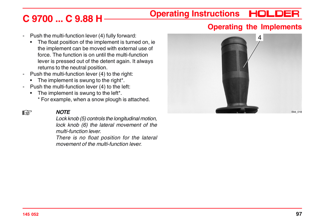
Push the multi-function lever 4 fully forward
Operating the Implements
C 9700 ... C 9.88 H
Operating Instructions
Multi-function Lever Variant
Attachment
Operating the Implements
Table of Multi-function Lever Functions Variant
Motion
C 9700 ... C 9.88 H
Front Lift 2 - Shifting Left/Right
You can also select the function only temporarily by pressing lightly
Operating Instructions
C 9700 ... C 9.88 H
7 8
Front Lift 3 - Lateral Tilt
Operating Instructions
Operating Instructions
Activating Functions Operation
C 9700 ... C 9.88 H
Operating the Implements
Operating Instructions
Operating the PTO
C 9700 ... C 9.88 H
Operating the Implements
C 9700 ... C 9.88 H
Engaging the Front PTO
Never engage the PTO with the engine off
Operating Instructions
selector lever 4 located at the articulated Ein
Engaging the Rear PTO
The rear PTO can be engaged with PTO
joint. The lever positions are shown on the plate
Operating Instructions
Operating the Hydraulic Carrier* Power Lifter
C 9700 ... C 9.88 H
Operating the Implements
C 9700 ... C 9.88 H
Road Travel with Carrier
Operation with Carrier
Operating Instructions
C 9700 ... C 9.88 H
Operating Variable Pump* for Implements setting from 0 to 100 litres
Turn on the starting safety switch 7 only at low engine speed
Operating Instructions
C 9700 ... C 9.88 H
Increase the engine speed, but then increase the oil flow only slowly
Turning Off the Variable Pump for Implements
Operating Instructions
Increase the speed of the engine slowly
Operating the Power Hydraulics* 75 L Fixed Flow
Turn on the starting safety switch only at a low engine speed
C 9700 ... C 9.88 H
Operating Instructions
Turning Off the Power Hydraulics
C 9700 ... C 9.88 H
Operating the Implements
C 9700 ... C 9.88 H
Operating the Hydraulic Dumper
Make sure no-one standing behind the truck can get hurt
Operating Instructions
lated
Turn on the starting safety switch only at low engine speed
Operating the Oil Circulating Device* Rear, Unregu
C 9700 ... C 9.88 H
Operating Instructions
Turning off the Oil Circulating Device
C 9700 ... C 9.88 H
Operating the Implements
C 9700 ... C 9.88 H
Operating Priority Flow Valve
Turn on the starting safety switch only at a low engine speed
Operating Instructions
Operating Instructions
Turning Off the Priority Flow Valve
C 9700 ... C 9.88 H
Operating the Implements
C 9700 ... C 9.88 H
Operating priority flow valve
Turn on the starting safety switch only at a low engine speed
Operating Instructions
Operating the Implements
C 9700 ... C 9.88 H
Operating Instructions
Turning Off the Priority Flow Valve
Operating the roof hatch Opening the roof hatch
Other Activities
Operating the Drivers Cab
Removing the roof hatch
Front Windshield Wiper/Washer
Other activities
Turning on the Windshield Wiper/Washer
RearWiper/Washer
Lights
Turn the preheat/starter switch to position
To use the headlight flasher, operate the signal lever up
Turning On and Operating the Lights
C 9700 ... C 9.88 H
9 17 10
16 15
Operating Instructions
Turning on the Upper Lights
Right and Left Turn Signal
Other activities
The functions high beam and headlight flasher
C 9700 ... C 9.88 H
Turning on the Hazard Warning Flasher System
Turning on the Rotating Beacon
Operating Instructions
Interior Light
Turning on the Flood Light
The flood light should not be used in the public traffic area
Turning on the Interior Light
Radio* and Loudspeaker Operating the Radio
The loudspeakers 3 are installed at the rear in the roof of the cabin
Power Socket Connecting Equipment to Power Socket
There is a separate operating manual for the radio
Turning on the Heating
Heating
Heating and Ventilation
The cabin heater is heated by the engine
The fresh air blower top has 2 speeds
The heater blower has two speeds
Turning on the Ventilation System
C 9700 ... C 9.88 H
the air conditioning
Operating the Air Conditioner
A separate operating manual is supplied for
Please observe the instructions in this manual for operation
C 9700 ... C 9.88 H
Fuses
Fuses for the Tractor
Operating Instructions
The fuses for the cabin are located on the console at the top right
To gain access to the fuses, remove the cover
Fuses for the Cabin
Fuse for Air Conditioning
Page
Stopping theTractor
Taking out of Operation
Leaving the Tractor
C 9700 ... C 9.88 H
Do not leave the cabin without taking the ignition key
Taking out of Operation
Parking
Leaving theTractor
Table of Trailers
Permissible Total Weight
Trailers, Towing
Type of Trailer
Bearing Load
Trailers, Towing
Operating the Trailer Hitch, Attaching Trailers
Be sure no-one is standing between the tractor and trailer
Operating Instructions
Driving with Trailers
C 9700 ... C 9.88 H
Trailers, Towing
Page
Instructions for Loading
Transport, Loading, Towing
Instructions forTransport
C 9700 ... C 9.88 H
C 9700 ... C 9.88 H
Transport, hoisting, towing
Instructions forTowing
Operating Instructions
C 9700 ... C 9.88 H
Indicators, Adjustments
Adjusting the Speedometer
Operating Instructions
Page
Problems in Electronic and Hydraulic Drive System
Problems, Cause, Remedy
Problems in Engine and Exhaust Gas Turbo- charger
Malfunction
C 9700 ... C 9.88 H
Problem
Malfunctions, cause, remedy
Operating Instructions
C 9700 ... C 9.88 H
Malfunctions, cause, remedy
Problem
Operating Instructions
Operating Instructions
Problem
C 9700 ... C 9.88 H
Malfunctions, cause, remedy
C 9700 ... C 9.88 H
Problems in the Hydraulic System and Steering
Problem
Operating Instructions
Operating Instructions
Problem
C 9700 ... C 9.88 H
Malfunctions, cause, remedy
Service
General Remarks on Maintenance
Qualification of the Service Personnel
How to Value the Tractor?
Service
General Remarks on Maintenance
The following services were carried out
Hours of
General Remarks on Maintenance
Safety Notes for Maintenance
Handling fuels and lubricants
C 9700 ... C 9.88 H
Operating Instructions
General Remarks on Maintenance
C 9700 ... C 9.88 H
Work on the Electrical Equipment
General Remarks on Maintenance
Disconnect the battery ground lead
C 9700 ... C 9.88 H
Jacking Up
The weight to be lifted should not exceed the
Jack Lifting Points
permissible load capacity of the jack
C 9700 ... C 9.88 H
Securing the Frame Loading Platform
General Remarks on Maintenance
Operating Instructions
Page
C 9700 ... C 9.88 H
Maintenance Schedule
Maintenance during the First Period of Operation
Operating Instructions
Periodic Maintenance
Maintenance Schedule
Regular Maintenance
Service and Inspection
Service and Inspection
Maintenance Schedule
Periodic Maintenance
Maintenance every 1000 service hours
Page
Check the Engine for Leaks
Maintenance during the First Period of Operation
Maintenance after the First 50 Operating Hours
C 9700 ... C 9.88 H
Page
C 9700 ... C 9.88 H
Maintenance as Required
Adjusting the Speedometer
Operating Instructions
Type
Maintenance as required
Switch Arrangement
Gearbox
Replacement
Checking the Air Cleaner System
Cleaning
Maintenance as required
Maintenance as required
Changing the Hydraulic Oil Return Filter for the Variable Pump
Observe the instructions for handling fuels and lubricants
C 9700 ... C 9.88 H
C 9700 ... C 9.88 H
Changing the Hydraulic Oil Return Filter for Power Hydraulics
Maintenance as required
Operating Instructions
Page
Cleaning the Cooling System Cleaning with Compressed Air
Maintenance According to Intervals
Maintenance Every 125 Service Hours
Cleaning with Cold Cleaner orWater Jet
Checking the High Pressure Hoses
Maintenance Every 125 Service Hours
Checking the Battery and Cable Connections
C 9700 ... C 9.88 H
Filling quantity
Checking the Steering Cylinders and Orbitrol
Checking the Brake Fluid Level for the Foot Brake
Do not mix different kinds of brake fluids
Checking the Braking System
Checking the Clutch if mechanical gearbox is fitted
Checking the PTO clutch
Do not operate the tractor with a defective braking system
C 9700 ... C 9.88 H
Tractor Lubrication
Maintenance Every 125 Service Hours
Operating Instructions
Checking the Electrical System
Tightening Nuts and Bolts
Tightening the Wheel Nuts
Maintenance Every 125 Service Hours
Maintenance Every 125 Service Hours
Cleaning the Upper Fresh Air Filter
Cleaning the Lower Fresh Air Filter
C 9700 ... C 9.88 H
Page
Changing the Engine Oil
Maintenance Every 500 Service Hours
Danger of scalding when draining hot engine oil
8.75 litres 2.31 USGAL
Observe the instructions on handling fuels and lubricants
Maintenance Every 500 Service Hours
Changing the Engine Oil Filter
Checking Hose Couplings for Leaks
C 9700 ... C 9.88 H
Changing the Hydraulic Oil Pressure Filter Drive Hydraulics
Maintenance Every 500 Service Hours
Operating Instructions
C 9700 ... C 9.88 H
Changing the Hydraulic Oil Pressure Filter Imple- ment Hydraulics
Maintenance Every 500 Service Hours
Operating Instructions
C 9700 ... C 9.88 H
Maintenance Every 500 Service Hours
Checking the Heating System
Operating Instructions
Page
For the sake of your safety, observe the fol- lowing instructions
Maintenance Every 1000 Service Hours
Checking the Battery
Checking Valve Clearance
Cleaning/Replacing the Fuel Pump Strainer
Maintenance Every 1000 Service Hours
Adjust V-belt tension only when the engine is shut off
Checking V-belt Tension and Condition
C 9700 ... C 9.88 H
Lubricating the Cardan Shaft
Maintenance Every 1000 Service Hours
Operating Instructions
Page
Hours
Maintenance Every 1500 Service
Danger of scalding when draining of hot gear oil
Change the Front Gearbox Oil Including Axles
Filling Oil Gearbox Only
Maintenance Every 1500 Service Hours
Filling Oil Hydrostatic Drive Only
approx. 10.9 litres 2.88 USGAL
Changing the Rear Gearbox Oil Including Offset
Change the gear oil only when still warm
Danger of scalding when draining hot gear oil
Axles
Operating Instructions
Maintenance Every 1500 Service Hours
C 9700 ... C 9.88 H
Filling quantity
Change the hydraulic oil while still warm
Danger of scalding when draining hot hydraulic oil
Changing the Drive Hydraulics Oil
Maintenance Every 1500 Service Hours
approx. 19 litres 5.02 USGAL
The air in the hydraulic system is bled automatically
Fill recommended hydraulic oil through the filler neck
Maintenance Every 1500 Service Hours
Maintenance Every 1500 Service Hours
Changing the Implement Hydraulics Oil
Secure the dump body loading platform* against accidental lowering
Danger of scalding when draining hot hydraulic oil
Cleaning
Checking or Cleaning the Implement Hydraulics Suction Filter
Maintenance Every 1500 Service Hours
Replacement
Operating Instructions
Maintenance Every 1500 Service Hours
C 9700 ... C 9.88 H
Filling quantity
C 9700 ... C 9.88 H
Maintenance Every 1500 Service Hours
Changing the Hydraulic Oil Return Filter for Power Hydraulics
Operating Instructions
Checking the Injection Nozzles
Maintenance Every 3000 Service Hours
When replacing the toothed belt, also replace the idler pulley
This work may only be carried out by an authorized workshop
Page
Laying Up
Annual Maintenance
Maintenance Every 2 Years
Examination of Implement Hydraulics Oil Samples
Page
Engine Preservation
Putting the Tractor Back in Service after a Lay-up
Laying Up
C 9700 ... C 9.88 H
Operating Instructions
Removing Engine Preservation
C 9700 ... C 9.88 H
Laying Up
Manufacturer
Recommended Fuels and Lubricants
Recommended Hydraulic and Gear Oils
Recommended Hydraulic Oil
Recommended Lubricating
Recommended Fuels and Lubricants
Recommended Engine Oils and Lubricants
Recommended Lubricant
Recommended Oil
Recommended Fuels and Lubricants
Recommended Engine Oils and Lubricants continued
Lubricants
C 9700/9800 H
Maintenance data
Filling Quantities
C 9.72/83 H
Hexagon Screws and Studs
Maintenance data
TighteningTorques
Gearbox, Axles, Wheels
Maintenance data
List of Replacement Parts
Order No
C 9700 ... C 9.88 H
Rating
Bulbs 12
Lights
Maintenance data
C 9700 ... C 9.88 H
Technical Data of Engine
Maintenance data
Operating Instructions
C 9700 ... C 9.88 H
Maintenance data
Engine Specifications
Operating Instructions
C 9700 ... C 9.88 H
Fuel System
Maintenance data
Operating Instructions
Operating Instructions
Alphabetical Index
C 9700 ... C 9.88 H
Operating Instructions
Index
C 9700 ... C 9.88 H
Index
C 9700 ... C 9.88 H
Operating Instructions
Drive Range Pre-selection Lever between Seats
Index
C 9700 ... C 9.88 H
Operating Instructions
Operating Instructions
Maintenance after the First 50 Operating Hours
C 9700 ... C 9.88 H
Index
Index
C 9700 ... C 9.88 H
Operating Instructions
Setting the Working Speed of Programs 3 and
Safety Instructions for Handling Fuels and Oils
Safety Instructions for Handling Implements
C 9700 ... C 9.88 H
Index
C 9700 ... C 9.88 H
Operating Instructions
Tractors for farming and forestry also with implements