2)5VDC Output Checks: There are seven 5VDC circuits on the appliance, "DRAIN" position through control switch,
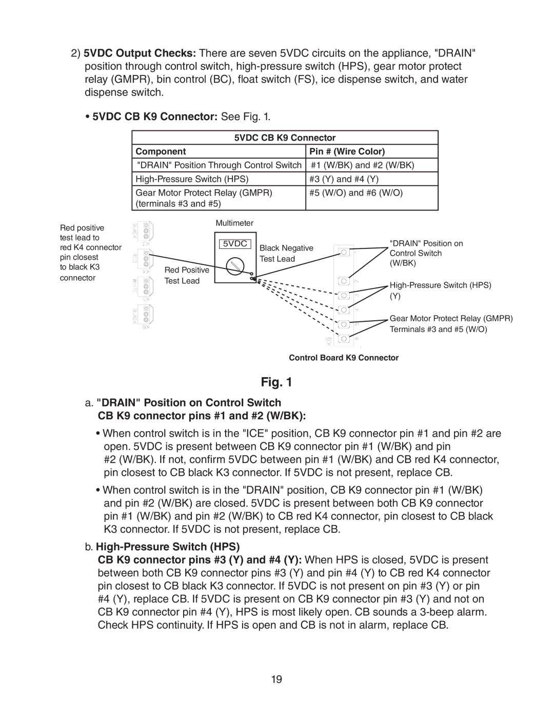
•5VDC CB K9 Connector: See Fig. 1.
5VDC CB K9 Connector
Component | Pin # (Wire Color) |
|
|
"DRAIN" Position Through Control Switch | #1 (W/BK) and #2 (W/BK) |
#3 (Y) and #4 (Y) | |
|
|
Gear Motor Protect Relay (GMPR) | #5 (W/O) and #6 (W/O) |
(terminals #3 and #5) |
|
|
|
Red positive test lead to
red K4 connector pin closest
to black K3 connector
Red Positive Test Lead
Multimeter |
5VDC |
Black Negative Test Lead
"DRAIN" Position on Control Switch (W/BK)
(Y)
![]() Gear Motor Protect Relay (GMPR) Terminals #3 and #5 (W/O)
Gear Motor Protect Relay (GMPR) Terminals #3 and #5 (W/O)
Control Board K9 Connector
Fig. 1
a. "DRAIN" Position on Control Switch
CB K9 connector pins #1 and #2 (W/BK):
•When control switch is in the "ICE" position, CB K9 connector pin #1 and pin #2 are open. 5VDC is present between CB K9 connector pin #1 (W/BK) and pin
#2 (W/BK). If not, confirm 5VDC between pin #1 (W/BK) and CB red K4 connector, pin closest to CB black K3 connector. If 5VDC is not present, replace CB.
•When control switch is in the "DRAIN" position, CB K9 connector pin #1 (W/BK) and pin #2 (W/BK) are closed. 5VDC is present between both CB K9 connector pin #1 (W/BK) and pin #2 (W/BK) to CB red K4 connector, pin closest to CB black K3 connector. If 5VDC is not present, replace CB.
b.High-Pressure Switch (HPS)
CB K9 connector pins #3 (Y) and #4 (Y): When HPS is closed, 5VDC is present between both CB K9 connector pins #3 (Y) and pin #4 (Y) to CB red K4 connector pin closest to CB black K3 connector. If 5VDC is not present on pin #3 (Y) or pin #4 (Y), replace CB. If 5VDC is present on CB K9 connector pin #3 (Y) and not on CB K9 connector pin #4 (Y), HPS is most likely open. CB sounds a
19