c. Gear Motor Protect Relay (GMPR)
CB K9 connector pins #5 (W/O) and #6 (W/O): When GMPR is de‑energized, GMPR terminals #3 and #5 are open and 5VDC is present between
CB K9 connector pin #5 (W/O) and CB red K4 connector pin closest to CB black K3 connector. If 5VDC is not present, replace CB. When GMPR is energized, GMPR terminals #3 and #5 are closed and 5VDC is present between CB K9 connector pin #5 (W/O) and pin #6 (W/O) to CB red K4 connector pin closest to CB black
K3 connector. If GM is energized and GMPR terminals #3 & #5 are open, an
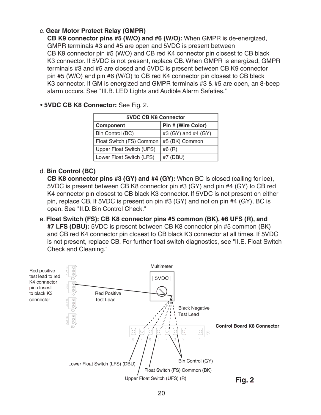
•5VDC CB K8 Connector: See Fig. 2.
5VDC CB K8 Connector
Component | Pin # (Wire Color) |
|
|
Bin Control (BC) | #3 (GY) and #4 (GY) |
Float Switch (FS) Common | #5 (BK) Common |
|
|
Upper Float Switch (UFS) | #6 (R) |
|
|
Lower Float Switch (LFS) | #7 (DBU) |
|
|
d. Bin Control (BC)
CB K8 connector pins #3 (GY) and #4 (GY): When BC is closed (calling for ice), 5VDC is present between CB K8 connector pin #3 (GY) and pin #4 (GY) to CB red K4 connector pin closest to CB black K3 connector. If 5VDC is not present on either pin, replace CB. If 5VDC is present on pin #3 (GY) and not on pin #4 (GY), BC is open. See "II.D. Bin Control Check."
e. Float Switch (FS): CB K8 connector pins #5 common (BK), #6 UFS (R), and #7 LFS (DBU): 5VDC is present between CB K8 connector pin #5 common (BK) and CB red K4 connector pin closest to CB black K3 connector at all times. If 5VDC is not present, replace CB. For further float switch diagnostics, see "II.E. Float Switch Check and Cleaning."
Red positive test lead to red K4 connector pin closest
to black K3 connector
Red Positive Test Lead
Multimeter |
5VDC |
Black Negative
Test Lead
Control Board K8 Connector
Lower Float Switch (LFS) (DBU) | Bin Control (GY) |
| |
| Float Switch (FS) Common (BK) |
Upper Float Switch (UFS) (R) | Fig. 2 |
|
20