F. Diagnostic Tables
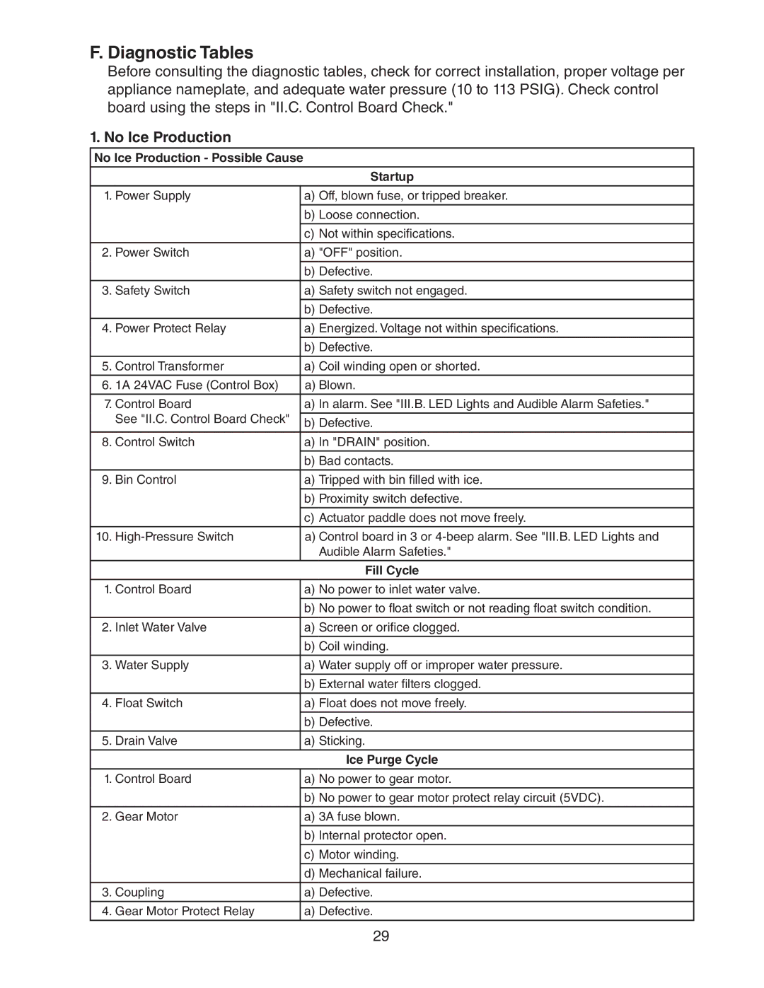
Before consulting the diagnostic tables, check for correct installation, proper voltage per appliance nameplate, and adequate water pressure (10 to 113 PSIG). Check control board using the steps in "II.C. Control Board Check."
1. No Ice Production
No Ice Production - Possible Cause
| Startup | |
|
| |
1. Power Supply | a) Off, blown fuse, or tripped breaker. | |
|
| |
| b) Loose connection. | |
| c) Not within specifications. | |
|
| |
2. Power Switch | a) "OFF" position. | |
|
| |
| b) Defective. | |
|
| |
3. Safety Switch | a) Safety switch not engaged. | |
| b) Defective. | |
|
| |
4. Power Protect Relay | a) Energized. Voltage not within specifications. | |
|
| |
| b) Defective. | |
|
| |
5. Control Transformer | a) Coil winding open or shorted. | |
6. 1A 24VAC Fuse (Control Box) | a) Blown. | |
|
| |
7. Control Board | a) In alarm. See "III.B. LED Lights and Audible Alarm Safeties." | |
See "II.C. Control Board Check" |
| |
b) Defective. | ||
| ||
|
| |
8. Control Switch | a) In "DRAIN" position. | |
| b) Bad contacts. | |
|
| |
9. Bin Control | a) Tripped with bin filled with ice. | |
|
| |
| b) Proximity switch defective. | |
|
| |
| c) Actuator paddle does not move freely. | |
10. | a) Control board in 3 or | |
| Audible Alarm Safeties." | |
|
| |
| Fill Cycle | |
|
| |
1. Control Board | a) No power to inlet water valve. | |
|
| |
| b) No power to float switch or not reading float switch condition. | |
|
| |
2. Inlet Water Valve | a) Screen or orifice clogged. | |
| b) Coil winding. | |
|
| |
3. Water Supply | a) Water supply off or improper water pressure. | |
|
| |
| b) External water filters clogged. | |
|
| |
4. Float Switch | a) Float does not move freely. | |
| b) Defective. | |
|
| |
5. Drain Valve | a) Sticking. | |
|
| |
| Ice Purge Cycle | |
|
| |
1. Control Board | a) No power to gear motor. | |
| b) No power to gear motor protect relay circuit (5VDC). | |
|
| |
2. Gear Motor | a) 3A fuse blown. | |
|
| |
| b) Internal protector open. | |
|
| |
| c) Motor winding. | |
| d) Mechanical failure. | |
|
| |
3. Coupling | a) Defective. | |
|
| |
4. Gear Motor Protect Relay | a) Defective. | |
|
|
29