D. Power Switch, Control Switch, and Dispense Mode Switch
The power switch, control switch, and dispense mode switch are used to control the operation of the appliance.
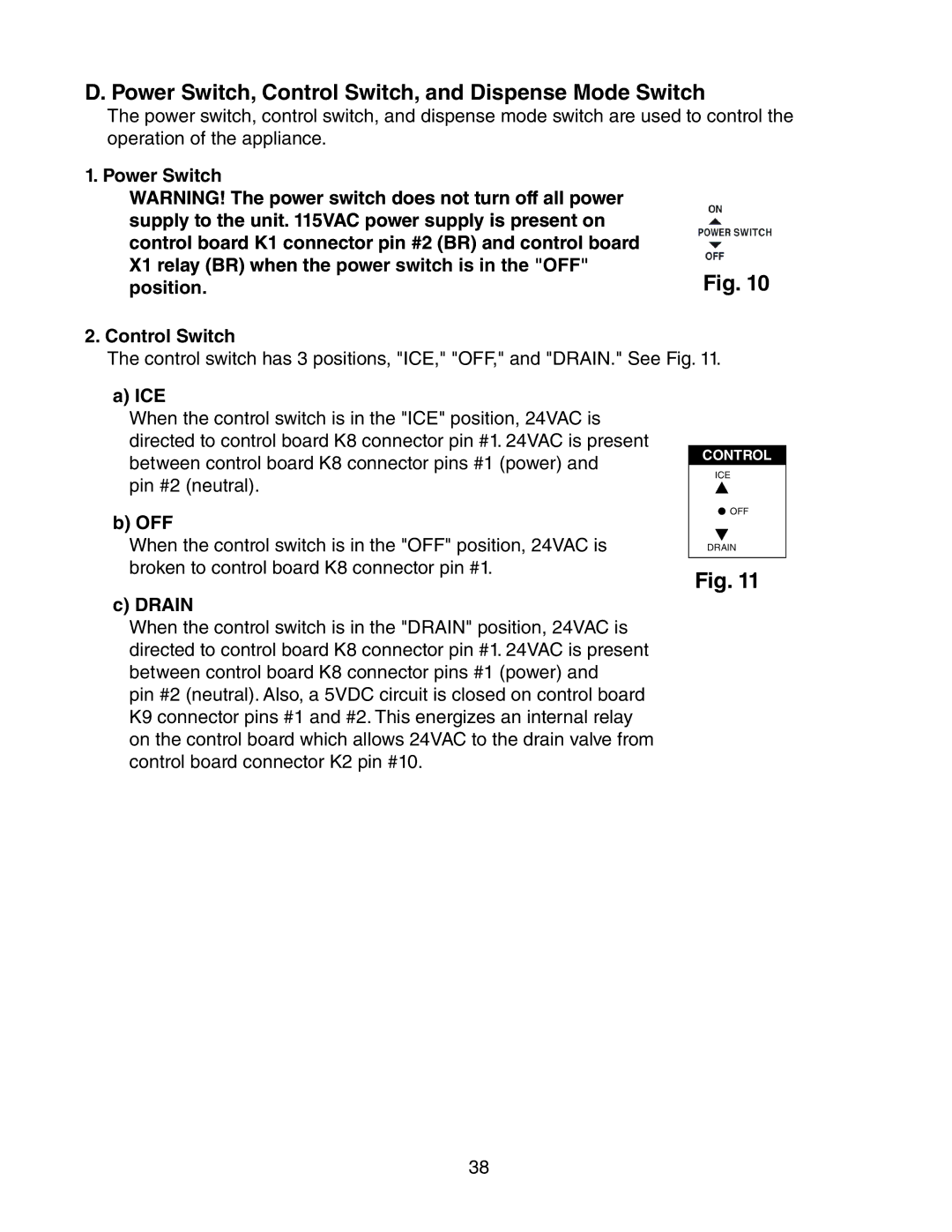
1. Power Switch |
|
WARNING! The power switch does not turn off all power |
|
supply to the unit. 115VAC power supply is present on |
|
control board K1 connector pin #2 (BR) and control board |
|
X1 relay (BR) when the power switch is in the "OFF" | Fig. 10 |
position. |
2. Control Switch
The control switch has 3 positions, "ICE," "OFF," and "DRAIN." See Fig. 11.
a) ICE
When the control switch is in the "ICE" position, 24VAC is directed to control board K8 connector pin #1. 24VAC is present between control board K8 connector pins #1 (power) and
pin #2 (neutral).
b) OFF
When the control switch is in the "OFF" position, 24VAC is broken to control board K8 connector pin #1.
CONTROL
ICE
![]() OFF
OFF
DRAIN
Fig. 11
c) DRAIN
When the control switch is in the "DRAIN" position, 24VAC is directed to control board K8 connector pin #1. 24VAC is present between control board K8 connector pins #1 (power) and
pin #2 (neutral). Also, a 5VDC circuit is closed on control board K9 connector pins #1 and #2. This energizes an internal relay on the control board which allows 24VAC to the drain valve from control board connector K2 pin #10.
38
