18CHAPTER 2: INSTALLING THE ROUTER
■Cables
n
n
n
n
n
Ethernet cable
Console cable
AUX cable
Power supply (for the Router 5012), power cord and chassis ground wire
Interface cables for the selected interface modules
■Equipment
n
n
n
n
n
n
A router
Optional SICs and MIMs
Ethernet
Channel service unit/data service unit (CSU/DSU) or other data communications equipment (DCE) equipment (such as a modem)
Configuration terminal, such as a PC
Additional equipment for the selected interface modules
1
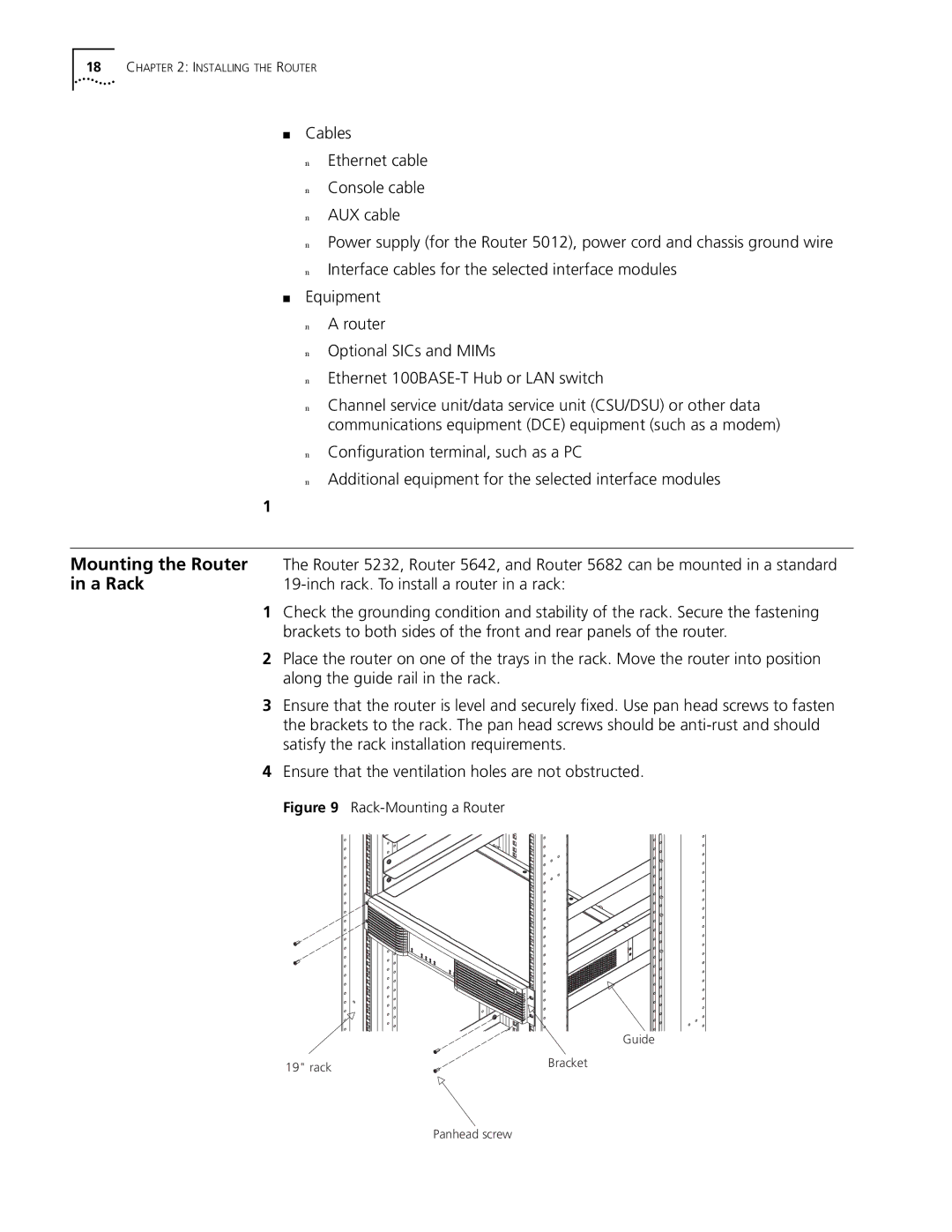
Mounting the Router | The Router 5232, Router 5642, and Router 5682 can be mounted in a standard |
in a Rack | |
1 | Check the grounding condition and stability of the rack. Secure the fastening |
| brackets to both sides of the front and rear panels of the router. |
2 | Place the router on one of the trays in the rack. Move the router into position |
| along the guide rail in the rack. |
3 | Ensure that the router is level and securely fixed. Use pan head screws to fasten |
| the brackets to the rack. The pan head screws should be |
| satisfy the rack installation requirements. |
4 | Ensure that the ventilation holes are not obstructed. |
Figure 9 Rack-Mounting a Router
Guide
19" rack | Bracket |
|
Panhead screw