Dumb Terminal Adapter 55
Dumb Terminal Adapter
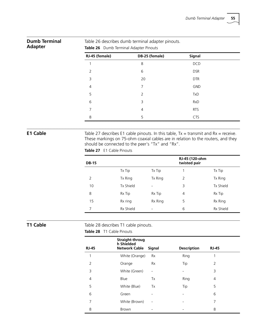
Table 26 describes dumb terminal adapter pinouts.
Table 26 Dumb Terminal Adapter Pinouts
Signal | ||
|
|
|
1 | 8 | DCD |
2 | 6 | DSR |
3 | 20 | DTR |
4 | 7 | GND |
5 | 2 | TxD |
6 | 3 | RxD |
7 | 4 | RTS |
8 | 5 | CTS |
|
|
|
E1 Cable | Table 27 describes E1 cable pinouts. In this table, Tx = transmit and Rx = receive. |
| These markings on |
| should be connected to the peer's “Tx” and “Rx”. |
| Table 27 E1 Cable Pinouts |
|
| BNC |
| |
| coaxial cable) | twisted pair |
| |
|
|
|
|
|
9 | Tx Tip | Tx Tip | 1 | Tx Tip |
2 | Tx Ring | Tx Ring | 2 | Tx Ring |
10 | Tx Shield | - | 3 | Tx Shield |
8 | Rx Tip | Rx Tip | 4 | Rx Tip |
15 | Rx ring | Rx Ring | 5 | Rx Ring |
7 | Rx Shield | - | 6 | Rx Shield |
|
|
|
|
|
T1 Cable | Table 28 describes T1 cable pinouts. |
|
| |
| Table 28 T1 Cable Pinouts |
|
| |
|
|
|
|
|
|
|
|
| |
|
| h Shielded |
|
|
| Network Cable Signal | Description | ||
1 | White (Orange) | Rx | Ring | 1 |
2 | Orange | Rx | Tip | 2 |
3 | White (Green) | - | - | 3 |
4 | Blue | Tx | Ring | 4 |
5 | White (Blue) | Tx | Tip | 5 |
6 | Green | - | - | 6 |
7 | White (Brown) | - | - | 7 |
8 | Brown | - | - | 8 |
|
|
|
|
|