Serial Interface Cable | 51 |
At the network end, the connector is different for each type of cable, as described in the following list:
■V.24
■V.24
■V.35 DTE cable —
■V.35 DCE cable —
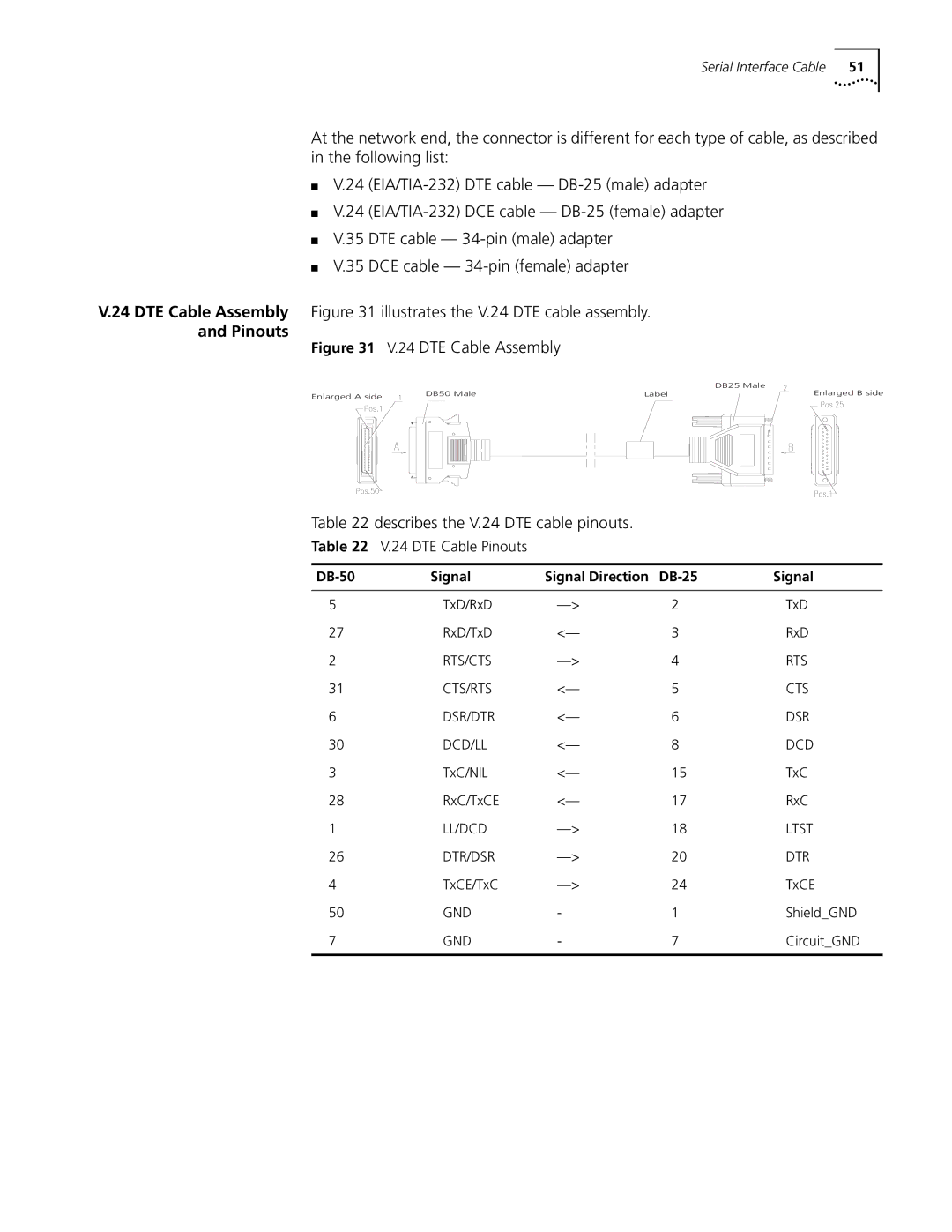
V.24 DTE Cable Assembly Figure 31 illustrates the V.24 DTE cable assembly.
and Pinouts
Figure 31 V.24 DTE Cable Assembly
|
|
| DB25 Male |
Enlarged A side | DB50 Male | Label | Enlarged B side |
|
|
|
Table 22 describes the V.24 DTE cable pinouts.
Table 22 V.24 DTE Cable Pinouts
| Signal | Signal Direction |
| Signal |
|
|
|
|
|
5 | TxD/RxD | 2 | TxD | |
27 | RxD/TxD | <— | 3 | RxD |
2 | RTS/CTS | 4 | RTS | |
31 | CTS/RTS | <— | 5 | CTS |
6 | DSR/DTR | <— | 6 | DSR |
30 | DCD/LL | <— | 8 | DCD |
3 | TxC/NIL | <— | 15 | TxC |
28 | RxC/TxCE | <— | 17 | RxC |
1 | LL/DCD | 18 | LTST | |
26 | DTR/DSR | 20 | DTR | |
4 | TxCE/TxC | 24 | TxCE | |
50 | GND | - | 1 | Shield_GND |
7 | GND | - | 7 | Circuit_GND |
|
|
|
|
|