52APPENDIX A: CABLE SPECIFICATIONS
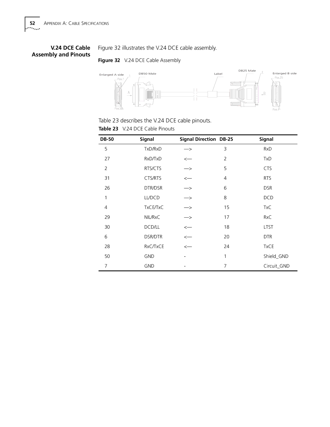
V.24 DCE Cable Figure 32 illustrates the V.24 DCE cable assembly.
Assembly and Pinouts
Figure 32 V.24 DCE Cable Assembly
|
|
| DB25 Male |
Enlarged A side | DB50 Male | Label | Enlarged B side |
|
|
|
Table 23 describes the V.24 DCE cable pinouts.
Table 23 V.24 DCE Cable Pinouts
| Signal | Signal Direction | Signal | |
|
|
|
|
|
5 | TxD/RxD | 3 | RxD | |
27 | RxD/TxD | <— | 2 | TxD |
2 | RTS/CTS | 5 | CTS | |
31 | CTS/RTS | <— | 4 | RTS |
26 | DTR/DSR | 6 | DSR | |
1 | LL/DCD | 8 | DCD | |
4 | TxCE/TxC | 15 | TxC | |
29 | NIL/RxC | 17 | RxC | |
30 | DCD/LL | <— | 18 | LTST |
6 | DSR/DTR | <— | 20 | DTR |
28 | RxC/TxCE | <— | 24 | TxCE |
50 | GND | - | 1 | Shield_GND |
7 | GND | - | 7 | Circuit_GND |
|
|
|
|
|