HP AdvanceStack Internet Router
Page
Support is as close As the World Wide Web
Additional HP Support Services
HP AdvanceStack Internet Router
Installation Guide
Publication Number
Contents
Verifying Network Connectivity Getting More Information
Configuring the HP AdvanceStack Internet Router
Cable Specifications
Page
HP AdvanceStack Internet Router Overview
HP AdvanceStack Internet Router Overview
Hardware Features
Software Features
Compression
Includes switching
Cables and Adapters
Ordering Information
Cisco Systems Contact Information
Documentation and Software
Cisco Systems, Inc West Tasman Drive San Jose, CA
Tel Nets Fax
Verifying Included Parts
Installation
Installing the HP AdvanceStack Internet Router
Modem for remote access optional
Required Tools and Parts
Preparing to Connect to a Network
Specification High-Capacitance Cable Low-Capacitance Cable
Isdn BRI Cable Specifications S/T Cable
Isdn Connections
Typical DTE and DCE Devices
Synchronous Serial Connections
Device Type Gender Typical Devices
EIA/TIA-232 Speed and Distance Limitations
Or other DCE device
Data Rate Baud Distance Feet Distance Meters
U T I O N
Console and Auxiliary Port Considerations
Console Port Connections
While you are installing the module
Installing the Module
Circuitry on the boards
Installation
Connecting to a WAN
Connecting to the Network
Connecting the Isdn BRI Port to an NT1 Device
Connecting the Console Terminal and Modem
Connecting the Console Terminal
Connecting a Modem to the Auxiliary Port
What to Do After Installing the Router Hardware
Configuration
Booting the Router for the First Time
Begin to configure the router
Configuring the Router for the First Time
Configuring the HP AdvanceStack Internet Router
Using the System Configuration Dialog
On the console screen
Parity, and 2 stop bits
Reflect the screen displays on your console
OK?
Enter the enable and virtual terminal passwords
Enter an enable secret password
Country Isdn Switch Type Description
Isdn Switch Type
Press Return or enter yes to configure serial port
Configuring Ethernet or VG Interfaces
Configuration
Prompt changes to the privileged Exec prompt
Using Configuration Mode
Router will now boot with the configuration you entered
Using AutoInstall
Cisco IOS Modes of Operation
Cisco IOS Software Basics
Interface serial 0 command to
Mode Usage How to Enter the Mode Prompt Operation
Cisco IOS Operating Modes
Getting Context-Sensitive Help
Saving Configuration Changes
Configuring Isdn
Router config# username targetrouter password abc
Enter the exit command to exit interface configuration mode
Enter the exit command to exit global configuration mode
Example Isdn Configuration
Router# config term
Example Isdn Configuration
Verifying Network Connectivity
Configuration
Getting More Information
Reading the LEDs
Maintenance
LEDs on the Host Device Front Panel
Troubleshooting
State Description
Isdn BRI
LEDs on the HP AdvanceStack Internet Router Front Panel
Recovering Lost Passwords
Upgrading the Boot ROMs
Boot ROMs and ignore Nvram
Signal to the router
Enter the initialize command to initialize the router
Ration Dialog appears
Nvram
Passwords, if they are not encrypted, and proceed to step
Are different
Or replace a password, proceed to and log
Press Ctrl-Z to exit configuration mode
Reboot the router
Configuration register value you set in step
0x2102 is a combination of settings
Virtual Configuration Register Settings
Virtual Configuration Register Bit Meanings
Bit No.a Hexadecimal Meaning
Virtual configuration register is stored in Nvram
Changing Configuration Register Settings
Explanation of Boot Field Configuration Register Bits 00 to
Boot Field Boot Process
Virtual Configuration Register Bit Meanings
Boot field number, a hyphen, and the processor type
Default Boot Filenames
Overrides the default boot filename
Action or Filename Bit
Baud Bit
Bit Address net host
Copying a Cisco IOS Image to Flash Memory
Enabling Booting from Flash Memory
Following messages display
Command reference publications
System reboots using the new image in Flash memory
Back of HP Switching Hub
Inserting the HP Internet Router Module into an HP Remote 2C
Router to Router Connections
Cable Specifications
Console and Auxiliary Port Signals Pinouts
Identifying a Roll-Over Cable
Cable Specifications
Console Port Signals and Pinouts
Figure A-2. Connecting the Auxiliary Port to a Modem
Auxiliary Port Signals and Pinouts
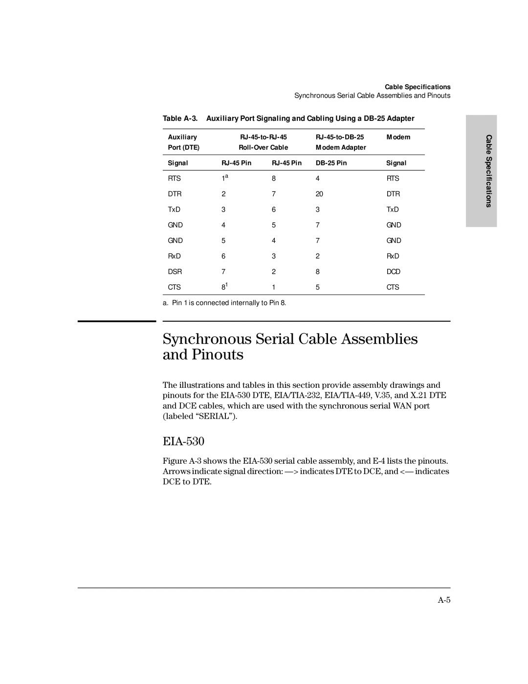
EIA-530
Synchronous Serial Cable Assemblies and Pinouts
Figure A-3. EIA-530 Serial Cable Assembly
Table A-4.EIA-530 DTE Cable Pinouts DB-60 to DB-25
60 Pin Signal 25 Pin DTE DCEa
Direction
EIA/TIA-232
Table A-5. EIA/TIA-232 DCE Cable Pinouts DB-60 to DB-25
60 Pin Signal Description Direction 25 Pin
Cable
Table A-6. EIA/TIA-232 DCE Cable Pinouts DB-60 to DB-25
EIA/TIA-449
Table A-7. EIA/TIA-449 DTE Cable Pinouts DB-60 to DB-37
60 Pin Signal Description Direction 37 Pin
Table A-8. EIA/TIA-449 DCE Cable Pinouts DB-60 to DB-37
Indicates DTE to DCE, and indicates DCE to DTE
Figure A-6. V.35 Cable Assembly
Table A-9. V.35 DTE Cable Pinouts DB-60 to 34-Pin
60 Pin Signal Description Direction 34 Pin
Cable
Table A-10. V.35 DCE Cable Pinouts DB-60 to 34-Pin
Figure A-7. X.21 Cable Assembly Cable Specifications
Table A-11. X-21 DTE Cable Pinouts DB-60 to DB-15
60 Pin Signal Description Direction 15 Pin
Table A-12. X.21 DCE Cable Pinouts DB-60 to DB-15
Table A-13. BRI Port RJ-45 Pinout
Isdn BRI Port and Cable Pinouts
RJ-45 TE b NT c Polarity Pin a
HP J3138A Specifications
Power Consumption
Physical
Environmental
Electromagnetic
Connectors
IEC 950 1991 + A1, A2 / .EN60950 I 1992 + A1, A2
Safety Information
Safety and Regulatory Statements
Informations concernant la sécurité
Safety and Regulatory Statements
Hinweise zur Sicherheit
Sicherheitssymbole
Simboli di sicurezza
Considerazioni sulla sicurezza
Símbolos de seguridad
Consideraciones sobre seguridad
Statements
Safety Information Japanese
Regulatory Statements
No repairs can be done by the customer
Canada
European Community
Unshielded cables and EN55022
Page
Index
Index
Index
See also Isdn BRI
Setup
Page
Page
J3138-90003