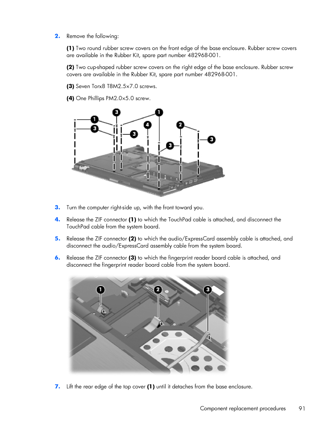
2.Remove the following:
(1)Two round rubber screw covers on the front edge of the base enclosure. Rubber screw covers are available in the Rubber Kit, spare part number
(2)Two
(3)Seven Torx8 T8M2.5×7.0 screws.
(4)One Phillips PM2.0×5.0 screw.
3.Turn the computer
4.Release the ZIF connector (1) to which the TouchPad cable is attached, and disconnect the TouchPad cable from the system board.
5.Release the ZIF connector (2) to which the audio/ExpressCard assembly cable is attached, and disconnect the audio/ExpressCard assembly cable from the system board.
6.Release the ZIF connector (3) to which the fingerprint reader board cable is attached, and disconnect the fingerprint reader board cable from the system board.
7.Lift the rear edge of the top cover (1) until it detaches from the base enclosure.
Component replacement procedures | 91 |
