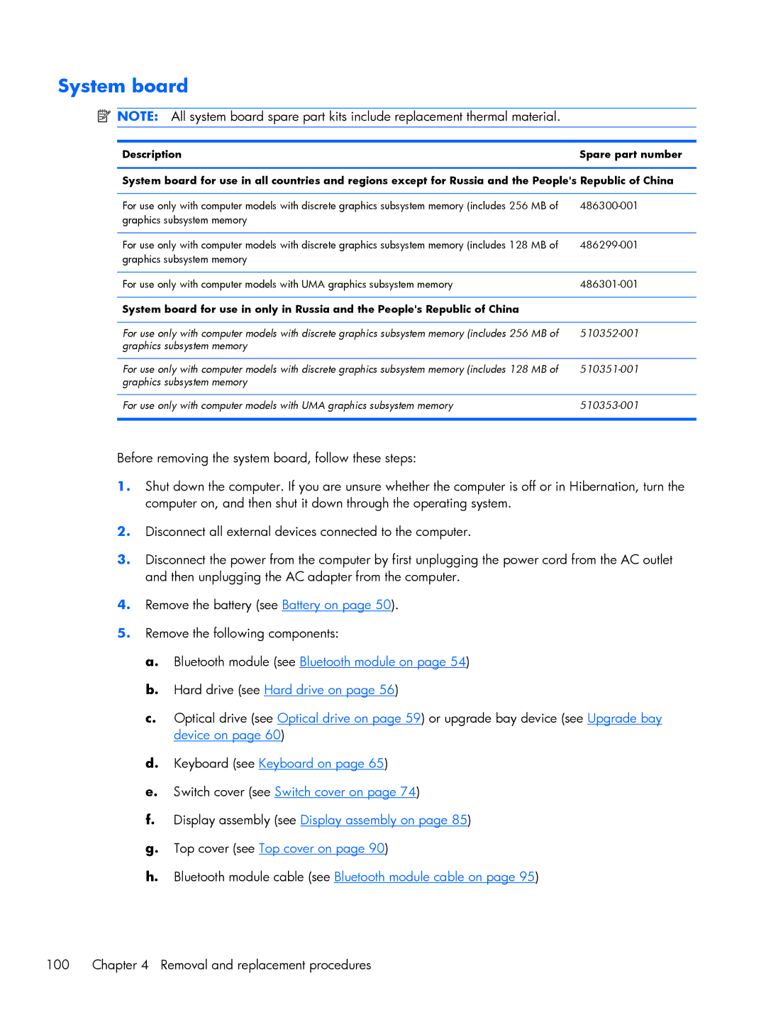
System board
![]() NOTE: All system board spare part kits include replacement thermal material.
NOTE: All system board spare part kits include replacement thermal material.
DescriptionSpare part number
System board for use in all countries and regions except for Russia and the People's Republic of China
For use only with computer models with discrete graphics subsystem memory (includes 256 MB of | |
graphics subsystem memory |
|
|
|
For use only with computer models with discrete graphics subsystem memory (includes 128 MB of | |
graphics subsystem memory |
|
|
|
For use only with computer models with UMA graphics subsystem memory | |
|
|
System board for use in only in Russia and the People's Republic of China |
|
|
|
For use only with computer models with discrete graphics subsystem memory (includes 256 MB of | |
graphics subsystem memory |
|
|
|
For use only with computer models with discrete graphics subsystem memory (includes 128 MB of | |
graphics subsystem memory |
|
|
|
For use only with computer models with UMA graphics subsystem memory | |
|
|
Before removing the system board, follow these steps:
1.Shut down the computer. If you are unsure whether the computer is off or in Hibernation, turn the computer on, and then shut it down through the operating system.
2.Disconnect all external devices connected to the computer.
3.Disconnect the power from the computer by first unplugging the power cord from the AC outlet and then unplugging the AC adapter from the computer.
4.Remove the battery (see Battery on page 50).
5.Remove the following components:
a.Bluetooth module (see Bluetooth module on page 54)
b.Hard drive (see Hard drive on page 56)
c.Optical drive (see Optical drive on page 59) or upgrade bay device (see Upgrade bay device on page 60)
d.Keyboard (see Keyboard on page 65)
e.Switch cover (see Switch cover on page 74)
f.Display assembly (see Display assembly on page 85)
g.Top cover (see Top cover on page 90)
h.Bluetooth module cable (see Bluetooth module cable on page 95)
100 | Chapter 4 Removal and replacement procedures |
