4.Remove the battery (see Battery on page 50).
5.Remove the following:
a.Hard drive (see Hard drive on page 56)
b.Keyboard (see Keyboard on page 65)
c.Switch cover (see Switch cover on page 74)
d.Display assembly (see Display assembly on page 85)
e.Top cover (see Top cover on page 90)
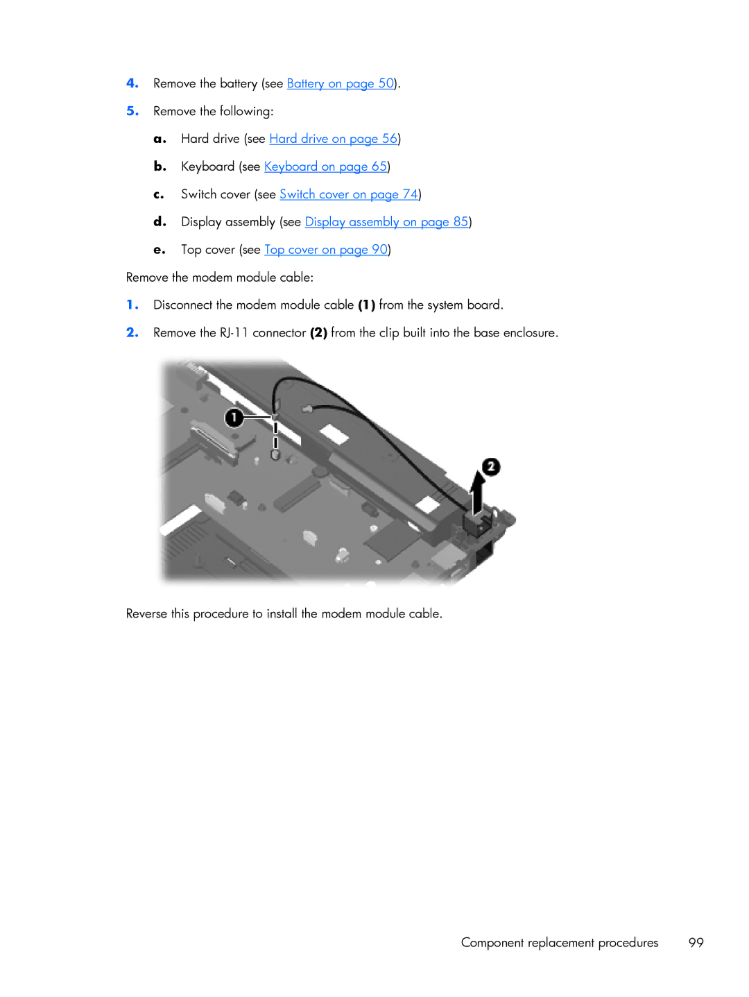
Remove the modem module cable:
1.Disconnect the modem module cable (1) from the system board.
2.Remove the
Reverse this procedure to install the modem module cable.
Component replacement procedures | 99 |
