HP OmniBook 800CS/CT
Page
Table of Contents
Hard Disk Drive Floppy Disk Drive CD-ROM Drive
OmniBook 800 External Features
List of Figures
Diagnostic Commands for Toggling Settings
List of Tables
Introduction
Resource Number/Address Comments
Page
Part Product Overview
1MB RAM
Feature OmniBook 800 with MMX F1360 F1171 F1175
What’s New
Product Features
OmniBook 800 External Features
Exploded Diagram
Product at a Glance
Parts Identification
Number Part Number Replaceable
2MB 1MB
Product Comparisons
HP OmniBook With MMX Technology
Dram
∙ RAM
IDE
Pcmcia
∙ PC ID
Battery and accessories On battery Accessories
Page
Page
Page
Part Troubleshooting
Post Beep Codes
Power-On Self-Test
Beep Codes
Message Possible Cause
Display Codes
Post Display Codes
No Bootable Floppy Drive 0 Installed
No Interrupts from Timer
DMA Controller Faulty
Faulty DMA page Registers
Main diagnostic screen
OmniBook Diagnostics
Running the diagnostics program
Main Diagnostic Screen Running selected tests
Special test hardware requirements
Alternative methods for running tests
Loop Back Connectors
Serial Loop Back Connector
Pcmcia Type III extender card
SyCard Solder Bridges
Switch Description
Command line options
Diagnotic Command Line Options
User interface commands
Commands for test selection
Diagnostic Test Selection Commands
Command Description
Mouse switch Key Action
Commands for toggling test settings
Diagnostic Commands for Toggling Settings
Diagnostic Hidden Commands
Commands for setting test parameters
Diagnostic Test Parameters
RAM, motherboard
Details on using the diagnostic tests
Cache
RAM, plug
Upper PC Card
Timers
Lower PC Card
Real time clock
IRQ controller
Battery
Serial port
Printer port
Hard disk
Text mode mouse test
Keyboard
OUT
TOP
BOT
Left
Mouse Test Screen text mode Graphic mode mouse sine test
Mouse Test Screen graphics mode
Text mouse and graphic sine mouse tests selected
Graphic draw screen mouse test selected
Audio
Display
Docked device
Scsi Hard disk
Dock keyboard
Dock Eeprom
Description of DMI
Contents of the DMI Package
Desktop Management Interface DMI
MIF
LAN
CD-ROM
Using the DMI Interface
Installing the DMI Package from Windows
Uninstalling the DMI Package from Windows
Setup and Configuration
SCU Main Screen
System Menu Settings
Boot Devices…
System Menu Screen
Date and Time…
Passwords…
Enable Cache
Status Panel Enable
Status Panel Settings…
PC ID
Password Configuration
System Password Matrix
Input/Output Menu Screen
Enabled IrDA IR
External Devices…
Audio Port…
Video Stretched
Power Menu Screen
Port Activity
IRQ3, IRQ4, IRQ5
IRQ7, IRQ9
Default Menu Screen
Default Menu Settings
Factory Default
Settings
Exit Menu Screen
Troubleshooting Tips
OmniBook Troubleshooting Tips
Symptom Call Center Repair Center
OmniBook Components
Power/battery
Computer won’t turn On/won’t boot
Lockup/computer freezes
Computer noisy but working
Miscellaneous
Symptom Call Center Repair Center
CD ROM Drive Troubleshooting
Bios
CD-ROM Troubleshooting Tips
Trouble Possible Causes Solutions
Resolving Docking Station Operating Problems
If an external PS/2 mouse or keyboard doesn’t work
Resolving OmniBook Docking Problems
If a network-enabled system locks up when rebooting
If your docking password isn’t accepted
If network connections don’t work
Page
Part Hardware Repair
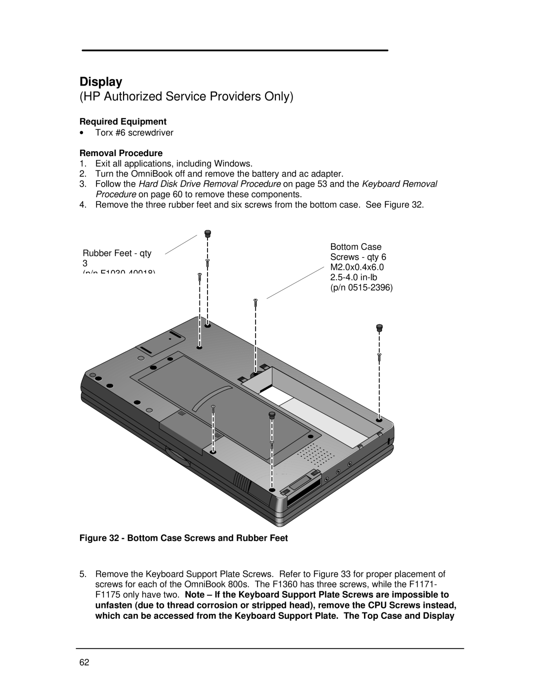
Required Equipment
Battery
Removal Procedure
Memory
16-MB Memory Modules
Removing the Memory Module Replacement Procedure
Hard Disk Drive
Hard Drive Screws
Folding the Keyboard Open
Discharge
Hard Drive Removal Replacement Procedure
Inserting the Hard Drive
Hard Disk Drive Breather Holes
IBM and Toshiba Hard Drive Breather Holes respectively
Removing the Mouse Replacement Procedure
Mouse
Battery Latch
Small Parts
Keyboard
Keyboard Screws
Securely into the zero insertion force connectors
Under the keyboard
Display
Bottom Case Screws and Rubber Feet
F1360 only F1171 F1175
Keyboard Support Plate Screws
Display Flex Cables
Top Case and Display Removal
Intel Inside Sticker Placement
Connector
CPU
Heat Transfer Disk
Heat Transfer Disk and Keyboard Support Insulator
Page
Logic PCA Board
Electronic Serial Number
Programming the Electronic Serial Number
Overriding an Incorrect Electronic Serial Number
Logic PCA Removal
Grommet and Bushing Placement
Paw Active
Paw Active Removal
Other Components and Accessories
Page
Page
Appendices
Appendix a Technical Specifications
Mass Storage Specifications
Hard Disk Drive
Floppy Disk Drive
Floppy Disk Drive Specifications
CD-ROM Drive Specifications
CD-ROM Drive
Inch Floppy Drive
System Resources
System Interrupts IRQs
Interrupts for F1171 F1175
Interrupts for F1360
DMA Channels
Memory Map
DMA Channels for F1171 F1175, and F1360
Memory Map for F1171 F1175
Addresses
O Address for F1171 F1175
Ffff
O Addresses for F1360
Appendix B Hewlett-Packard Password Removal Policy
Page
Appendix C Hewlett-Packard TFT Display Quality Statement
Appendix D OmniBook Diagnostics Bios Checksums
OmniBook F1171 F1175 Bios Checksums
Altera Boot Total SUM
OmniBook F1360 Bios Checksums
Appendix E OmniBook Diagnostics Error Messages
Bios flash roms
Hewlett-Packard supplied test messages
Fail C-F=XXXX#YYYY
Disk Drives Scsi HD / internal HD / Floppy
Scsi loopback test
Co-CPU test responses
Watergate Software supplied test messages
CPU test responses
VGA test responses
Memory test responses
Cache test responses
Timer chip test responses
Cmos RAM test responses
Sound test responses
Keyboard test responses
COM test responses
IRQ test resonses
DMA test responses
HD test responses
CD ROM test responses
F1175
Appendix F Part Numbers
F1171 F1360
External Battery
LI-ION Battery
CD-ROM Power Cable
SVC Kybrd Topcase
OB Lightweight
Setup Guide English
Setup Guide E,G,F,S,I
Setup Guide E,D,S,F,N
French
Italian
German
Spanish
Page
HP Part Number F1360-90049