Illustrated Parts Catalog
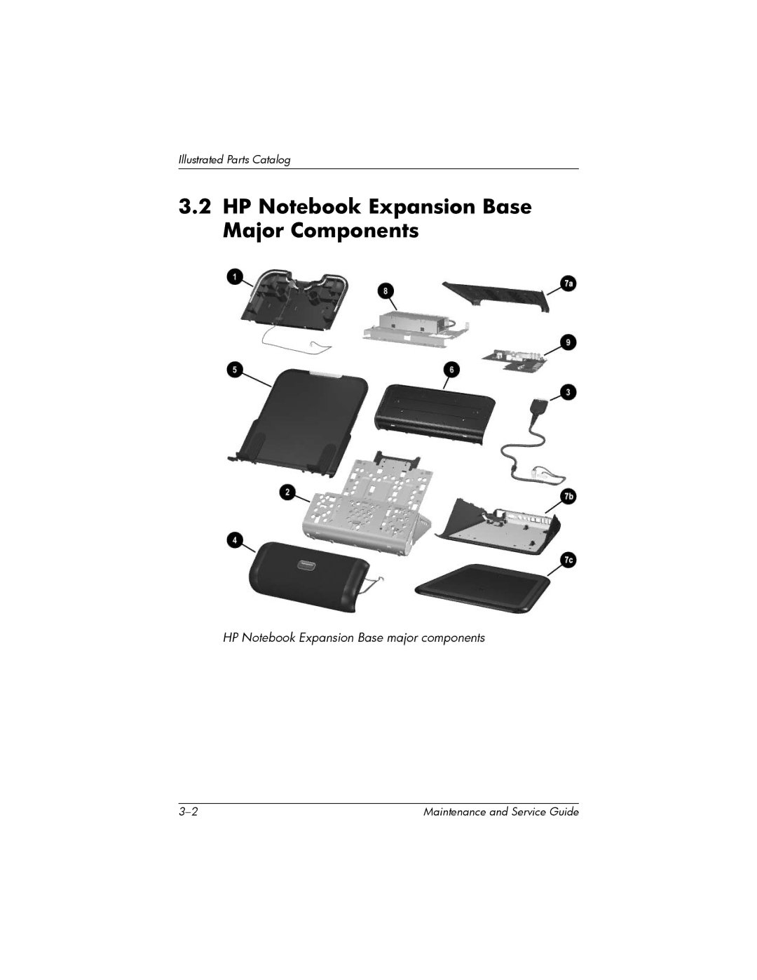
HP Notebook Expansion Base major components
3–2
Maintenance and Service Guide