Removal and Replacement Procedures
5.7 System Board
Spare Part Number Information
System board | |
|
|
1.Prepare the Expansion Base for disassembly (Section 5.3).
2.Remove the base plate (Section 5.4).
3.Remove the upper chassis (Section 5.5).
4.Remove the power supply (Section 5.6).
5.Position the base enclosure with the rear panel facing you.
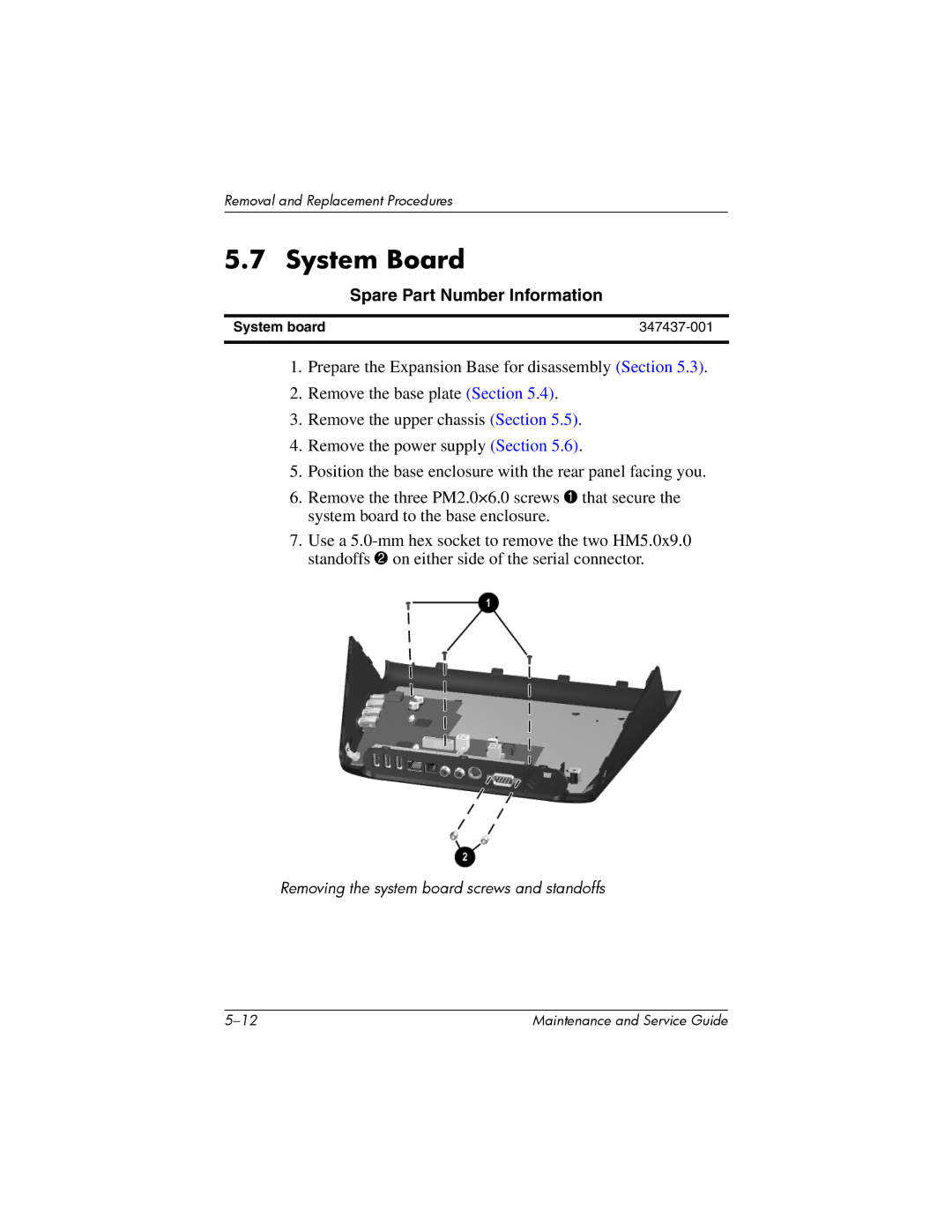
6.Remove the three PM2.0×6.0 screws 1 that secure the system board to the base enclosure.
7.Use a
Removing the system board screws and standoffs
Maintenance and Service Guide |