Manuals
/
HP
/
Computer Equipment
/
Laptop
HP
R3003US, R3065US, R3070US, R3060US, R3050US HP Notebook Expansion Base miscellaneous components
Models:
R3006AP
R3017AP
R3004XX
R3010EA
R3016AP
R3030US
R3000Z
R3004US
R3060EA
R3013AP
R3023AP
R3000T
R3038CL
R3050EA
R3009AP
R3024AP
R3010AP
R3056RS
R3070US
R3065US
R3019AP
R3002AP
R3003AP
R3050US
R3000 (AMD)
R3040EA
R3008AP
R3007AP
R3030EA
R3002
R3001
R3001US
R3060US
R3011AP
R3014AP
R3005AP
R3004AP
R3057EA
R3015AP
R3001AP
R3003US
R3003XX
1
21
74
74
Download
74 pages
43.39 Kb
18
19
20
21
22
23
24
25
Troubleshooting
Specification
Disassembly Sequence Chart
Wireless Accessories
Maintenance
Problems and Solutions
Connector Pin Assignments
Speaker Assembly
Workstation Precautions
Power cord
Page 21
Image 21
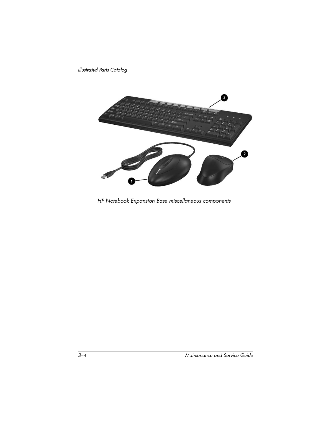
Illustrated Parts Catalog
HP Notebook Expansion Base miscellaneous components
3–4
Maintenance and Service Guide
Page 20
Page 22
Page 21
Image 21
Page 20
Page 22
Contents
Maintenance and Service Guide
Page
Contents
Screw Listing Index
Product Description
Features
External Components
Component Function
Front Components
Right-Side Components
Rear components
Rear Panel Components
Left-Side Components
Wireless Accessories
Wireless Accessories
Design Overview
Before Replacing Parts
Troubleshooting
Problems and Solutions
Power Problems and Solutions
Problem Possible Cause Solution
External Device Problems and Solutions
Serial Number Location
Illustrated Parts Catalog
HP Notebook Expansion Base Major Components
Description Number
Spare Part
HP Notebook Expansion Base miscellaneous components
Receiver
Item Description Number
Power cord
Removal and Replacement Preliminaries
Service Considerations
Tools Required
Plastic Parts
Preventing Electrostatic Damage
Packaging and Transporting Precautions
Workstation Precautions
Grounding Equipment and Methods
Static-Shielding Materials
Typical Electrostatic Voltage Levels
Event 10% 40% 55%
Material Use Voltage Protection Level
Removal and Replacement Procedures
Serial Number
Disassembly Sequence Chart
Disassembly Sequence Chart
# of Screws
Section Description Removed
Preparing the HP Notebook Expansion Base for Disassembly
Spare Part Number Information
Base Plate
Upper Chassis
Removing the rear cover
Disconnecting the cables from the system board
Reverse the above procedure to install the upper chassis
Power Supply
Reverse the above procedure to install the power supply
System Board
Reverse the above procedure to install the system board
Front Tray Cover
Reverse the above procedure to install the front tray cover
Back Panel
Expansion Cable
Speaker Assembly
Reverse the above procedure to install the speaker assembly
Front Case
HP Notebook Expansion Base
Specifications
Internal AC Adapter
Power supply
Table A-1 RJ-45 Network Interface
Connector Pin Assignments
Table A-3 Universal Serial Bus
Table A-2 RJ-11 Modem
Table A-5 Audio Line-Out
Table A-4 Video
Table A-6 Serial
Table A-8
Table A-7 Pdif Audio Line-Out
Power Cord Set Requirements
Conductor Power Cord Set
General Requirements
Country-Specific Requirements
Conductor Power Cord Set Requirements
Applicable Note
Country Accredited Agency Number
BSI
Screw Listing
Table C-1 Phillips PM2.5×17.0 Screw
Head
Color Qty Length Thread Width
Table C-2 Phillips PM2.0×6.0 Screw
Table C-2 Phillips PM2.0×6.0 Screw
Table C-2
Table C-4 HM5.0×9.0 Standoff
Table C-5 Phillips PM2.0×4.0 Screw
Table C-5 Phillips PM2.0x4.0 Screw
Table C-5 Phillips PM2.0×4.0 Screw
Table C-5 Phillips PM2.0×4.0 Screw
Table C-5 Phillips PM2.0×4.0 Screw
Table C-6 Phillips PM2.0×2.0 Screw
Index
Index
Maintenance and Service Guide Index-3
Top
Page
Image
Contents