Managing Serviceguard Twentieth Edition
Legal Notices
Contents
Contents
Planning and Documenting an HA Cluster
Contents
Building an HA Cluster Configuration 158
Contents
Configuring Packages and Their Services 227
Contents
Cluster and Package Maintenance 261
279
Troubleshooting Your Cluster 321
Contents
349
Integrating HA Applications with Serviceguard 354
Software Upgrades 357
IPv6 Network Support 378
Blank Planning Worksheets 369
Migrating from LVM to VxVM Data Storage 374
377
Index 398
Using Serviceguard Manager 385
396
Publishing History
Publishing History
Preface
Related Publications
Securing Serviceguard and other Serviceguard white papers
What is Serviceguard?
Serviceguard at a Glance
Shows what happens in a failover situation
Failover
Typical Cluster After Failover
About Veritas CFS and CVM from Symantec
Using SAM
Using Serviceguard Manager
Usr/sbin/sam -w
What are the Distributed Systems Administration Utilities?
Roadmap for Configuring Clusters and Packages
Tasks in Configuring a Serviceguard Cluster
Redundancy of Cluster Components
Understanding Serviceguard Hardware Configurations
Rules and Restrictions
Redundant Network Components
Redundant LANs
Redundant Ethernet Configuration
Restrictions
Cross-Subnet Configurations
Configuration Tasks
For legacy packages, see Configuring Cross-Subnet Failover
For More Information
Supported Disk Interfaces
Redundant Disk Storage
Replacing Failed Network Cards
About Multipathing
Disk Arrays using RAID Levels and Multiple Data Paths
Data Protection
Disk Mirroring
Replacing Failed I/O Cards
Monitoring LVM Disks Through Event Monitoring Service
Monitoring VxVM and CVM Disks
Replacing Failed Disk Mechanisms
Mirrored Disks Connected for High Availability
Sample Scsi Disk Configurations
Cluster with High Availability Disk Array
Sample Fibre Channel Disk Configuration
Larger Clusters
Redundant Power Supplies
Point to Point Connections to Storage Devices
Active/Standby Model
Eight-Node Cluster with XP or EMC Disk Array
Serviceguard Daemons
Understanding Serviceguard Software Components
Serviceguard Architecture
Cluster Daemon cmcld
Configuration Daemon cmclconfd
Cluster Object Manager Daemon cmomd
Cluster Logical Volume Manager Daemon cmlvmd
File Management Daemon cmfileassistd
Syslog Log Daemon cmlogd
Lock LUN Daemon cmdisklockd
Service Assistant Daemon cmserviced
Quorum Server Daemon qs
Network Manager Daemon cmnetd
CFS Components
Configuring the Cluster
How the Cluster Manager Works
Proxy Daemon cmproxyd
Manual Startup of Entire Cluster
Heartbeat Messages
Cluster Lock
Automatic Cluster Startup
Dynamic Cluster Re-formation
Cluster Quorum to Prevent Split-Brain Syndrome
Lock Requirements
Use of a Lock LUN or LVM Lock Disk as the Cluster Lock
Dual Lock Disk
Use of the Quorum Server as the Cluster Lock
Single Lock Disk or LUN
Quorum Server Operation
No Cluster Lock
Failover Packages
How the Package Manager Works
Package Types
Non-failover Packages
Failover Packages’ Switching Behavior
Deciding When and Where to Run and Halt Failover Packages
Before Package Switching
Automatic Rotating Standby
Package Configuration Data
Rotating Standby Configuration before Failover
Failback Policy
Configurednode Policy Packages after Failover
Automatic Failback Configuration After Failover
Using the Generic Resources Monitoring Service
Using Older Package Configuration Files
Understanding Serviceguard Software Components
See also Using EMS to Monitor Volume Groups
Using the Event Monitoring Service
Using the EMS HA Monitors
See also Using Generic Resources to Monitor Volume Groups
What Makes a Package Run?
How Packages Run
Legacy Package Time Line Showing Important Events
Before the Control Script Starts
Package Time Line Legacy Package
During Run Script Execution
Normal and Abnormal Exits from the Run Script
Service Startup with cmrunserv
While Services are Running
During Halt Script Execution
When a Package is Halted with a Command
Legacy Package Time Line for Halt Script Execution
Normal and Abnormal Exits from the Halt Script
Package Control Script Error and Exit Conditions
Error Conditions and Package Movement for Failover Packages
Stationary and Relocatable IP Addresses
How the Network Manager Works
Types of IP Addresses
Adding and Deleting Relocatable IP Addresses
Load Sharing
Monitoring LAN Interfaces and Detecting Failure Link Level
Local Switching
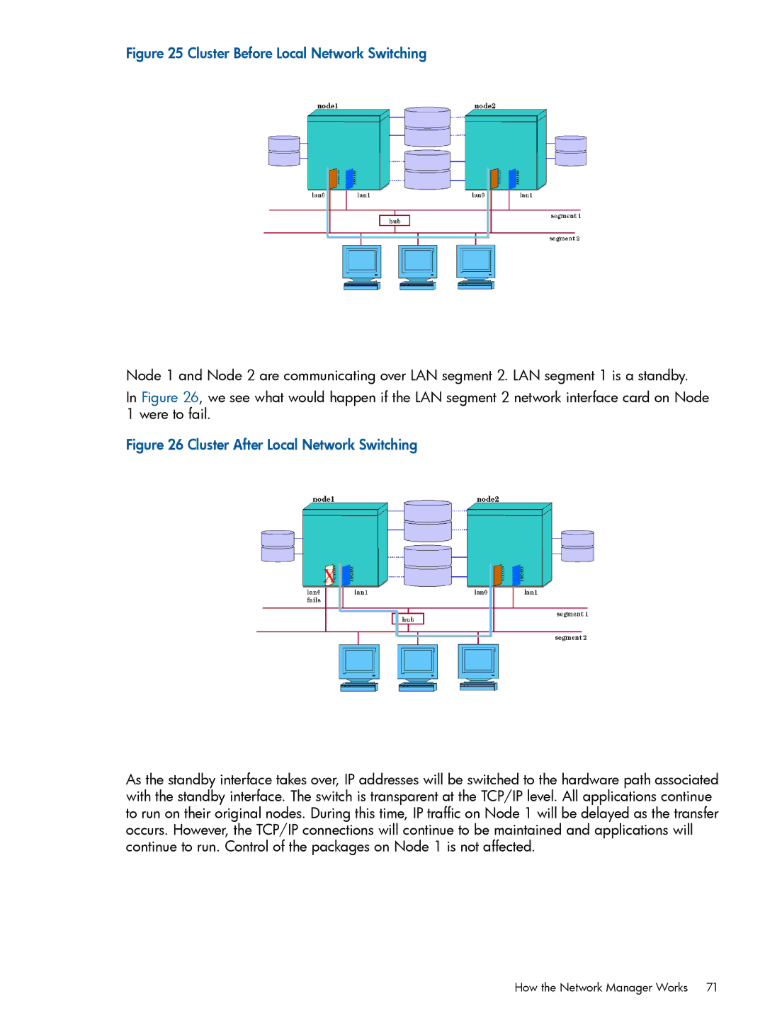
Cluster Before Local Network Switching
Cmmodnet -e interface
Where interface is the primary interface
Monitoring LAN Interfaces and Detecting Failure IP Level
Remote Switching
How the IP Monitor Works
Reasons To Use IP Monitoring
Failure and Recovery Detection Times
See also Reporting Link-Level and IP-Level Failures
Example 1 If Local Switching is Configured
Reporting Link-Level and IP-Level Failures
Constraints and Limitations
Cmmodnet -e lan2
Example 2 If There Is No Local Switching
Automatic Port Aggregation
Support for HP-UX Vlan
Vlan Configurations
What is VLAN?
Additional Heartbeat Requirements
Volume Managers for Data Storage
Configuration Restrictions
Types of Redundant Storage
White papers
About Device File Names Device Special Files
Examples of Mirrored Storage
Physical Disks Within Shared Storage Units
Examples of Storage on Disk Arrays
Multiple Devices Configured in Volume Groups
Multiple Paths to LUNs
Propagation of Disk Groups in VxVM
Types of Volume Manager
HP-UX Logical Volume Manager LVM
Veritas Volume Manager VxVM
For heartbeat requirements, see Redundant Heartbeat Subnets
Veritas Cluster Volume Manager CVM
Cluster Startup Time with CVM
Propagation of Disk Groups with CVM
Redundant Heartbeat Subnets
Comparison of Volume Managers
Pros and Cons of Volume Managers with Serviceguard
Example
System Reset When a Node Fails
What Happens when a Node Times Out
Responses to Failures
Responses to Hardware Failures
Responses to Package and Generic Resources Failures
Responses to Package and Service Failures
Network Communication Failure
Service Restarts
Planning for Expansion
Serviceguard Memory Requirements
Planning and Documenting an HA Cluster
General Planning
Hardware Planning
Sample Cluster Configuration
Nnn.nnn.nnn.nnn
SPU Information
Network Information
LAN Information
Scsi Addressing in Cluster Configuration
Under Cluster Configuration Parameters
Diskinfo
Disk I/O Information
Hardware Configuration Worksheet
Power Supply Planning
Cluster Lock Planning
Power Supply Configuration Worksheet
Quorum Server Worksheet
Using a Quorum Server
Cluster Lock Disk and Re-formation Time
LVM Planning
Using Generic Resources to Monitor Volume Groups
Using EMS to Monitor Volume Groups
LVM Worksheet
For more information, see Using the EMS HA Monitors
CVM and VxVM Planning
CVM and VxVM Worksheet
Cluster Configuration Planning
Points To Note
Where cDSFs Reside
About Cluster-wide Device Special Files cDSFs
Limitations of cDSFs
LVM Commands and cDSFs
About Easy Deployment
Limitations of Easy Deployment
Heartbeat Subnet and Cluster Re-formation Time
Advantages of Easy Deployment
Localhost ipv6-localhost ipv6-loopback
What Is IPv4-only Mode?
What Is IPv6-Only Mode?
Rules and Restrictions for IPv6-Only Mode
IPV6 or ANY
What Is Mixed Mode?
Recommendations for IPv6-Only Mode
Name of the cluster as it will appear in the output
Cluster Configuration Parameters
Rules and Restrictions for Mixed Mode
Cluster configuration file
Planning and Documenting an HA Cluster
99 and Specifying a Quorum Server
Happens when You Change the Quorum Configuration
Go/hpux-serviceguard-docs under HP Serviceguard
IPv4-Only,IPv6-Only, and Mixed Mode page 106 for
See also About Hostname Address Families IPv4-Only
Hpux-serviceguard-docs under HP Serviceguard
IPv6-Only, and Mixed Mode page 106 for important
Sitepreferred or
Configuration file see Configuring Packages
Their Services page 227 and these in turn must
Cluster Is Running
Configuration Planning page 125 must be specified
Cluster Configuration Planning
To that LAN, to risk timeout without being serviced
You cannot change the heartbeat configuration while
CVM/CFS on HP Serviceguard A.11.20 April
Protocols and services. RPC assumes that each network
Lock LUN page 189 for more information
Also What Happens when You Change the Quorum
Configuration Online page 49 for important information
See IPv6 Address Types
Failbackpolicy
When You Change the Quorum Configuration Online
Cluster is running, see Updating the Cluster Lock Disk
See About Package Weights page 144 for more
Planning and Documenting an HA Cluster
IP-Level Failures
See also What Happens when a Node Times Out
88, Cluster Daemon cmcld page 41,
69, Monitoring LAN Interfaces and Detecting
How Serviceguard will handle the recovery of the primary
Default is
Configuration file specifies one of two ways to decide
When a network interface card has failed
See Monitoring LAN Interfaces and Detecting Failure IP
Planning and Documenting an HA Cluster
Access Control Policies also known as Role Based Access
Package Configuration Planning
Cluster Configuration Next Step
Logical Volume and File System Planning
CVM 4.1 and later without CFS
CVM 4.1 and later with CFS
Using the Volume Monitor
About the Volume Monitor
Or --log-level
Or --help
Or --version
Or --log-file
Usr/sbin/cmvolmond -t 10 /dev/vg00/lvol1
Volumepath
Planning for NFS-mounted File Systems
Usr/sbin/cmvolmond /dev/vg01/lvol1 /dev/vg01/lvol2
Package Configuration Planning
Package Failover Behavior
Choosing Switching and Failover Behavior
Cmmakepkg -i $SGCONF/pkg1/pkg1.conf -m sg/genericresource
Parameters for Configuring Generic Resources
Configuring a Generic Resource
Extended generic resource
Cmapplyconf -P $SGCONF/pkg1/pkg1.conf
Cmcheckconf -v -P $SGCONF/pkg1/pkg1.conf
Cmsetresource -r sfmdisk -s up
Cmviewcl -v -f line -p pkg1 grep genericresource
Cmrunpkg pkg1
Cmgetresource -r sfmdisk
Online Reconfiguration of Generic Resources
Parameters for Configuring EMS Resources
Assume that we want to make pkg1 depend on pkg2
About Package Dependencies
Simple Dependencies
Rules for Simple Dependencies
Planning and Documenting an HA Cluster
Dragging Rules for Simple Dependencies
Planning and Documenting an HA Cluster
Extended Dependencies
Rules for Exclusionary Dependencies
See Rules for differentnode and anynode Dependencies
Rules for differentnode and anynode Dependencies
What Happens when a Package Fails
Cmmakepkg 1m manpage
About Package Weights
Package Weights and Node Capacities
Configuring Weights and Capacities
For pkg2
Weightname packagelimit weightvalue
Simple Method
Nodename node1 Capacityname packagelimit
Defining Capacities
Comprehensive Method
Points to Keep in Mind
Nodename node2
Clustername cluster23 Nodename node1
Defining Default Weights
Defining Weights
Weightname B Weightvalue
Weightname a Weightvalue
Weightname B Weightvalue Weightname a
Cmquerycl 1m manpage
Rules and Guidelines
About External Scripts
Pevmonitoringinterval
Using Serviceguard Commands in an External Script
Cmviewcl -v -f line displays a lasthaltfailed flag
Determining Why a Package Has Shut Down
About Cross-Subnet Failover
Lasthaltfailed
Implications for Application Deployment
Configuring a Package to Fail Over across Subnets Example
Configuring ipsubnetnode
Configuring a Package Next Steps
Configuring nodename
Configuring monitoredsubnetaccess
Planning for Changes in Cluster Size
Preparing Your Systems Configuring the Cluster
Building an HA Cluster Configuration
Installing and Updating Serviceguard
Where Serviceguard Files Are Kept
Etc/cmcluster.conf
Creating Cluster-wide Device Special Files cDSFs
Before You Start
Creating cDSFs for a Group of Nodes
Cmpreparecl -n node1 -n node2 -n node3 -n node4
Csshsetup -r node2
Csshsetup -r -f /etc/cmcluster/sshhosts
Cmpreparecl -n nodename -n nodename
Removing a Node from a cDSF Group
Using Easy Deployment
Displaying the cDSF Configuration
Adding a Node to a cDSF Group
Cmquerycl -N $SGCONF/mynetwork
Using Easy Deployment Commands to Configure the Cluster
For example
Preparing Your Systems
Building an HA Cluster Configuration
PVG bus1 /dev/cdisk/disk14 /dev/cdisk/disk15
Format for entries in cmclnodelist is as follows
Configuring Root-Level Access
Allowing Root Access to an Unconfigured Node
About identd
Ensuring that the Root User on Another Node Is Recognized
Any of the aliases. Examples
Configuring Name Resolution
Official hostname, as defined by hosts 4, for example
Safeguarding against Loss of Name Resolution Services
For NIS, enter two lines
Ensuring Consistency of Kernel Configuration
Enabling the Network Time Protocol
Tuning Network and Kernel Parameters
Make the new disk a boot disk
Creating Mirrors of Root Logical Volumes
Backing Up Cluster Lock Disk Information
Choosing Cluster Lock Disks
Setting Up a Lock LUN
This will create three device files, for example
Creating a Disk Partition on an HP Integrity System
Usr/sbin/idisk -w -p -f partition.txt /dev/rdsk/c1t4d0
Usr/sbin/idisk -w -p -f partition.txt /dev/rdisk/disk12
Defining the Lock LUN
Excluding Devices from Probing
Creating a Storage Infrastructure with LVM
Setting Up and Running the Quorum Server
Using the EMS Disk Monitor
Using the Generic Resources Disk Monitor
Creating Volume Groups
Using Mirrored Individual Data Disks
Lvchange -t 60 /dev/vg01/lvol1
Creating Logical Volumes
Setting Logical Volume Timeouts
Creating File Systems
Distributing the Volume Group
Distributing Volume Groups to Other Nodes
Verify the configuration
Deactivating the Volume Group
Create a directory to mount the disk
Deactivate the volume group on ftsys10
Still on ftsys9, copy the map file to ftsys10
Converting Disks from LVM to VxVM
Making Physical Volume Group Files Consistent
Creating Additional Volume Groups
Creating a Storage Infrastructure with VxVM
Creating Disk Groups
Initializing Disks for VxVM
Initializing Disks Previously Used by LVM
Re-Importing Disk Groups
Deporting Disk Groups
Cmquerycl -v -C $SGCONF/clust1.conf -n ftsys9 -n ftsys10
Configuring the Cluster
Clearimport at System Reboot Time
Here is an example of the command enter it all one line
Specifying the Address Family for the Heartbeat
Cmquerycl Options
Speeding up the Process
Specifying the Address Family for the Cluster Hostnames
Full Network Probing
Specifying a Lock Disk
Specifying the Cluster Lock
Generating a Network Template File
See also Choosing Cluster Lock Disks
Specifying a Lock LUN
Cmquerycl -v -n ftsys9 -n ftsys10
Vgchange -c y /dev/vglock
Will produce the output such as the following
Specifying a Quorum Server
Obtaining Cross-Subnet Information
Cmquerycl -q QSHost QSAddr -n ftsys9 -n ftsys10 -C
Configuring the Cluster
Identifying Heartbeat Subnets
Specifying Maximum Number of Configured Packages
Modifying the Membertimeout Parameter
Controlling Access to the Cluster
Access Roles
How Access Roles Work
Setting up Access-Control Policies
Levels of Access
Userrole must be one of these three values
Monitor Fulladmin Packageadmin
Username root
Username john Userhost bit
Role Conflicts
Package versus Cluster Roles
Adding Volume Groups
Verifying the Cluster Configuration
Distributing the Binary Configuration File
Differences between Legacy CFS and Modular CFS
Storing Volume Group and Cluster Lock Configuration Data
Modular CFS packages v/s Legacy CFS packages
Operational commands for Legacy CFS and Modular CFS
Delete a mount point, check point, or snapshot in a package
Cfscluster status
Cfscluster config -t 900 -s
Preparing the Cluster and the System Multi-node Package
Cfsdgadm display
Creating the Disk Groups
Creating the Disk Group Cluster Packages
Cfsdgadm add logdata all=sw
Vxprint logfiles
Creating Volumes
Use the vxprint command to verify
Cfsdgadm showpackage logdata
Cmmakepkg -m sg/cfsall /etc/cmcluster/cfspkg1.ascii
Create a package configuration file
For instructions on creating modular CFS packages, see
Cmapplyconf -P /etc/cmcluster/cfspkg1.ascii
Apply the package configuration file
Cmcheckconf -P /etc/cmcluster/cfspkg1.ascii
Cfsconcurrentmountunmountoperations
Cmviewcl
Bdf
Cvmconcurrentdgoperations
Current primary, a primary migration is triggered to
Cmmakepkg -m sg/cfsall /etc/cmcluster/ckpt1.ascii
Package. For more information, see the manpage
See the mountvxfs 1m manpage
Cmmakepkg -m sg/cfsall snap1.ascii
Create a package configuration file for the snapshot image
Vxassist -g cvmdg3 make vol1 100m vxvol -g cvmdg3 startall
Mountvxfs 1m manpage
Mount points
Snapshotmountoptions
Information about the mount options, see
Online reconfiguration of modular CFS package parameters
Cmcheckconf -P cfspkg1.ascii
Cmviewcl -v -f line -p cfspkg1
Verify the output
Apply the configuration
Cmapplyconf -P cfspkg1.ascii
Legacy Style of Packaging
Modular Style of Packaging
Managing Disk Groups and Mount Points Using Legacy Packages
Cfsmount /tmp/checklogfiles
Creating Checkpoint and Snapshot Packages for CFS
Fsckptadm -n create check2 /tmp/logdata/logfiles
Associate it with the cluster and mount it
Cfsmount /local/snap1 cmviewcl
It is persistent
Vxassist -g dg1 make vol1 100m vxvol -g dg1 startall
Associate it with the cluster
You need to do the tasks described in the following sections
Initializing Disks for CVM
Initializing the Veritas Volume Manager
Preparing the Cluster for Use with CVM
Identifying the Master Node
Mirror Detachment Policies with CVM
Adding Disk Groups to the Package Configuration
Usr/lib/vxvm/bin/vxdisksetup -i c4t3d4
Vxdg -s init logdata c0t3d2
Managing the Running Cluster
Using Dsau during Configuration
Checking Cluster Operation with Serviceguard Manager
Checking Cluster Operation with Serviceguard Commands
Setting up Autostart Features
Preventing Automatic Activation of LVM Volume Groups
Managing a Single-Node Cluster
Here is an example of the /etc/rc.config.d/cmcluster file
Changing the System Message
Change the cmclconfd entry in /etc/inetd.conf to
Deleting the Cluster Configuration
Disabling identd
Single-Node Operation
Building an HA Cluster Configuration
Configuring Packages and Their Services
Types of Package Failover, Multi-Node, System Multi-Node
Choosing Package Modules
Failoverpolicy Failbackpolicy Ipsubnet Ipaddress
Cmmakepkg -m sg/all $SGCONF/sg-all
Differences between Failover and Multi-Node Packages
Package Modules and Parameters
Base Package Modules
Optional Modules
Optional Package Modules
Base Modules
Locallanfailoverallowed
Externalscript
Package Parameter Explanations
Cmmakepkg $SGCONF/sg-all
Autorun
Nodefailfastenabled
Nodename
Haltscripttimeout
Runscripttimeout
Loglevel
Successorhalttimeout
Scriptlogfile
Operationsequence
Dependencyname
Priority
For more information, see About Package Dependencies
Dependencycondition
Dependencylocation
Specifies where the dependencycondition must be met
Weightname, weightvalue
Clusterinterconnectsubnet
Monitoredsubnetaccess
Locallanfailoverallowed
Monitoredsubnet
Ipsubnet Ipaddress
New for A.11.18 for both modular and legacy packages
Ipsubnet
Ipaddress
Servicename
See the package configuration file for more examples
Ipsubnetnode
Servicehalttimeout
Servicecmd
Servicerestart
Servicefailfastenabled
Genericresourceupcriteria
Defines when the status of a generic resource is evaluated
Genericresourceevaluationtype
Resourcestart
Resourcename
Name of a resource to be monitored
Resourcepollinginterval
Cannot lock /etc/lvmconf//lvmlock still trying
Enablethreadedvgchange
Resourceupvalue
Concurrentvgchangeoperations
Vxvolcmd
Vgchangecmd
Cvmactivationcmd
Vxvmdgretry
Killprocessesaccessingrawdevices
Cvmdg
Vxvmdg
Fsmountretrycount
Fsfsckopt -s Fstype vxfs
Concurrentfsckoperations
Concurrentmountandumountoperations
Fstype
Fsname
Fsserver
Fsdirectory
Pev
Fsmountopt
Fsumountopt
Fsfsckopt
Additional Parameters Used Only by Legacy Packages
Username
Userhost
Userrole
Mkdir $SGCONF/pkg1
Generating the Package Configuration File
Before You Start
Cmmakepkg Examples
Next Step
Editing the Configuration File
See About Package Dependencies page 137 for more information
Packagetype. Enter failover, multinode, or systemmultinode
Editing the Configuration File
Vg vg01 Vg vg02
Verifying and Applying the Package Configuration
# vxdg -tfC import dg01
Adding the Package to the Cluster
How Control Scripts Manage VxVM Disk Groups
Cmviewcl -r A.11.16
Cluster and Package Maintenance
Reviewing Cluster and Package Status
Viewing Dependencies
Node Status and State
Viewing CFS Multi-Node Information
Types of Cluster and Package States
Cluster Status
Reviewing Cluster and Package Status
Down
Unknown
Normal Running Status
Examples of Cluster and Package States
Failover and Failback Policies
CFS Package Status
Quorum Server Status
Status After Halting a Package
Then run cmviewcl -v, we’ll see
If we use the following command
Status After Moving the Package to Another Node
Status After Halting a Node
Status After Auto Run is Enabled
Output of the cmviewcl command is now as follows
After we halt ftsys10 with the following command
Viewing Information about System Multi-Node Packages
This output can be seen on both ftsys9 and ftsys10
Viewing Information about Unowned Packages
Cmviewcl -v -p SG-CFS-pkg
Checking Status of the Cluster File System CFS
Status of the Packages in a Cluster File System
Ftsys9 Sw sw
Status of CFS Modular Disk Group and Mount Point Packages
Cmviewcl -v -p mpdg1
Status of Legacy CVM Disk Group Packages
Cfsmntadm display -v /tmp/logdata/logfiles
Checking the Cluster Configuration and Components
Ftsys10
Status of Legacy CFS Mount Point Packages
User-created files if you specify them
Etc/nsswitch.conf Etc/services
Checking Cluster Components
Cmapplyconf 1m
Verifying Cluster Components
Run cmcheckconf -C
See the cron 1m manpage for more information
Setting up Periodic Cluster Verification
Managing the Cluster and Nodes
Limitations
Cmruncl -v -n ftsys9 -n ftsys10
Starting the Cluster When all Nodes are Down
Adding Previously Configured Nodes to a Running Cluster
Using Serviceguard Commands to Start the Cluster
Cmhaltnode -f -v ftsys9
Removing Nodes from Participation in a Running Cluster
Halting the Entire Cluster
Cmrunnode -v ftsys8
Rules and Restrictions
Automatically Restarting the Cluster
What You Can Do
Managing the Cluster and Nodes
Additional Points To Note
Halting the Cluster and Detaching its Packages
Halting a Node and Detaching its Packages
Halting a Detached Package
Cmrunnode node1
Managing Packages and Services
Starting a Package
Halting a Package that Has Dependencies
Using Serviceguard Commands to Start a Package
Halting a Package
Starting a Package that Has Dependencies
Moving a Failover Package
Changing Package Switching Behavior
Using Serviceguard Commands to Halt a Package
Changing Package Switching with Serviceguard Commands
Cmmodpkg -d -n lptest3 pkg1
Maintaining a Package Maintenance Mode
See Performing Maintenance Using Maintenance Mode
Cluster and Package Maintenance
Procedure
Performing Maintenance Using Maintenance Mode
Cmrunpkg -m sg/packageip pkg1
Excluding Modules in Partial-Startup Maintenance Mode
Types of Changes to the Cluster Configuration
Reconfiguring a Cluster
Cmrunpkg -e sg/service pkg1
Cmrunpkg -m sg/services -e sg/packageip pkg1
Previewing the Effect of Cluster Changes
Change to the Cluster Configuration
Cmmodpkg -e -t pkg1
Using Preview mode for Commands and in Serviceguard Manager
Mode see Maintaining a Package Maintenance Mode
What You Can Preview
You would see output something like this
Using cmeval
Cmeval -v newstate.in
Updating the Cluster Lock LUN Configuration Online
Updating the Cluster Lock Configuration
Reconfiguring a Halted Cluster
Updating the Cluster Lock Disk Configuration Online
Cmgetconf -c cluster1 temp.ascii
Reconfiguring a Running Cluster
Cmapplyconf -C clconfig.ascii
Adding Nodes to the Cluster While the Cluster is Running
What You Can Do
Cmquerycl -C clconfig.ascii -c cluster1 -n ftsys8 -n ftsys9
What You Must Keep in Mind
Example Adding a Heartbeat LAN
Cmquerycl -c cluster1 -C clconfig.ascii
Removing a LAN or Vlan Interface from a Node
Cmgetconf clconfig.ascii
See also Replacing LAN or Fibre Channel Cards
Changing the LVM Configuration while the Cluster is Running
Changing the VxVM or CVM Storage Configuration
Cmgetconf -c clustername clconfig.ascii
Configuring a Legacy Package
Creating the Legacy Package Configuration
Mkdir /etc/cmcluster/pkg1
Configuring a Package in Stages
Editing the Package Configuration File
Cluster and Package Maintenance
Cmmakepkg -s /etc/cmcluster/pkg1/pkg1.sh
Creating the Package Control Script
Customizing the Package Control Script
Support for Additional Products
Adding Serviceguard Commands in Customer Defined Functions
Cmcheckconf -v -P /etc/cmcluster/pkg1/pkg1.conf
Verifying the Package Configuration
Distributing the Configuration
Copying Package Control Scripts with HP-UX commands
Configuring nodename
Configuring Cross-Subnet Failover
IP0 = SUBNET0 IP1 = SUBNET1
Reconfiguring a Package
Configuring monitoredsubnetaccess
Creating Subnet-Specific Package Control Scripts
Cmgetconf -p pkg1 pkg1.conf
Reconfiguring a Package on a Running Cluster
Migrating a Legacy Package to a Modular Package
Adding a Package to a Running Cluster
Reconfiguring a Package on a Halted Cluster
Unmount the shared file system cfsumount mount point
Deleting a Package from a Running Cluster
Cmhaltpkg mypkg Cmdeleteconf -p mypkg
Cmapplyconf -v -P app1.conf
Cmmodpkg -R -s myservice pkg1
Resetting the Service Restart Counter
Allowable Package States During Reconfiguration
Types of Changes to Packages
Change servicerestart modular package
Locallanfailoverallowed
Change vxvolcmd
Cfsmountoptions
Changes that Will Trigger Warnings
Responding to Cluster Events
Single-Node Operation
Disabling Serviceguard
Removing Serviceguard from a System
Testing the Package Manager
Troubleshooting Your Cluster
Testing Cluster Operation
Start the Cluster using Serviceguard Manager
Monitoring Hardware
Testing the Cluster Manager
Testing the Network Manager
Hardware Monitors and Persistence Requests
Using System Fault Management Service
Using Event Monitoring Service
Using EMS Event Monitoring Service Hardware Monitors
Replacing Disks
Using HP Isee HP Instant Support Enterprise Edition
Replacing a Faulty Array Mechanism
Replacing a Faulty Mechanism in an HA Enclosure
Replacing a Lock LUN
Replacing a Lock Disk
Replacing Scsi Host Bus Adapters
Online Hardware Maintenance with In-line Scsi Terminator
Cmdisklock reset /dev/dsk/c0t1d1
Replacing I/O Cards
Replacing LAN or Fibre Channel Cards
Offline Replacement
Online Replacement
After Replacing the Card
Replacing a Failed Quorum Server System
Reviewing the System Log File
Troubleshooting Approaches
Using cmquerycl and cmcheckconf Using cmviewcl
Reviewing Package IP Addresses
Cmreadlog /var/opt/cmom/cmomd.log
Reviewing Object Manager Log Files
Sample System Log Entries
Following is an example of a successful package starting
Reviewing the System Multi-node Package Files
Reviewing Serviceguard Manager Log Files
Reviewing Configuration Files
Using the cmcheckconf Command
Serviceguard Command Hangs
Solving Problems
Using the cmviewconf Command
Reviewing the LAN Configuration
Nslookup ftsys9
Networking and Security Configuration Errors
Cluster Re-formations Caused by Temporary Conditions
Package Control Script Hangs or Failures
System Administration Errors
Fuser -kulogical-volume umount logical-volume
Llt, gab Vxfen W cvm Cfs
Problems with Cluster File System CFS
Force Import and Deport After Node Failure
Problems with VxVM Disk Groups
Package Movement Errors
Node and Network Failures
Access denied to quorum server
Troubleshooting the Quorum Server
Authorization File Problems
Timeout Problems
Messages
Enterprise Cluster Master Toolkit
Automating Application Operation
Designing Highly Available Cluster Applications
Define Application Startup and Shutdown
Controlling the Speed of Application Failover
Insulate Users from Outages
Minimize Data Loss
Use Raw Volumes
Replicate Non-Data File Systems
Evaluate the Use of JFS
Balance Checkpoint Frequency with Performance
Use Restartable Transactions
Use Checkpoints
Design for Multiple Servers
Avoid Node-Specific Information
Designing Applications to Run on Multiple Systems
Design for Replicated Data Sites
Allow Multiple Instances on Same System
Avoid Using SPU IDs or MAC Addresses
Assign Unique Names to Applications
Obtain Enough IP Addresses
Bind to Relocatable IP Addresses
Use uname2 With Care
Bind to a Fixed Port
Call bind before connect
Give Each Application its Own Volume Group
Use Multiple Destinations for SNA Applications
Avoid File Locking
Help menu for ndd -h ipstrongesmodel
Etc/rc.config.d/nddconf as follows
Usr/sbin/route add net default 128.17.17.1 1 source
Restoring Client Connections
Usr/sbin/route delete net default 128.17.17.1 1 source
Be Able to Monitor Applications
Handling Application Failures
Create Applications to be Failure Tolerant
Do Not Change the Data Layout Between Releases
Reducing Time Needed for Application Upgrades and Patches
Provide for Rolling Upgrades
Minimizing Planned Downtime
Documenting Maintenance Operations
Providing Online Application Reconfiguration
Defining Baseline Application Behavior on a Single System
Integrating HA Applications with Serviceguard
Checklist for Integrating HA Applications
Integrating HA Applications in Multiple Systems
Move it back
Testing the Cluster
Special Considerations for Upgrade to Serviceguard A.11.19
Software Upgrades
Special Considerations for Upgrade to Serviceguard A.11.20
Rolling Upgrade Using DRD
Types of Upgrade
How To Tell when the Cluster Re-formation Is Complete
Rolling Upgrade
Non-Rolling Upgrade Using DRD
Guidelines for Rolling Upgrade
Restrictions for DRD Upgrades
Non-Rolling Upgrade
Limitations of Rolling Upgrades
Performing a Rolling Upgrade
Migrating cmclnodelist entries from A.11.15 or earlier
Running the Rolling Upgrade
Keeping Kernels Consistent
Running the Rolling Upgrade Using DRD
Performing a Rolling Upgrade Using DRD
Halt the first node, as follows
Example of a Rolling Upgrade
Step
Running Cluster with Packages Moved to Node
Repeat the process on node 2. Halt the node, as follows
Node 1 Rejoining the Cluster
Performing a Non-Rolling Upgrade
Guidelines for Non-Rolling Upgrade
Steps for a Non-Rolling Upgrade Using DRD
Performing a Non-Rolling Upgrade Using DRD
Limitations of Non-Rolling Upgrades using DRD
Checklist for Migration
Guidelines for Migrating a Cluster with Cold Install
Worksheet for Hardware Planning
Power Supply Worksheet
Blank Planning Worksheets
Quorum Server Worksheet
LVM Volume Group and Physical Volume Worksheet
VxVM Disk Group and Disk Worksheet
Cluster Configuration Worksheet
Package Configuration Worksheet
Package Configuration Worksheet
Loading VxVM
Migrating Volume Groups
Migrating from LVM to VxVM Data Storage
Mntdg0202, respectively
Customizing Packages for VxVM
Restart the package
Removing LVM Volume Groups
Customizing Packages for CVM
Migrating from Legacy CFS Packages to Modular CFS Packages
Textual Representation of IPv6 Addresses
IPv6 Network Support
IPv6 Address Types
IPv4 Compatible IPv6 Addresses
IPv6 Address Prefix
Unicast Addresses
IPv4 and IPv6 Compatibility
Multicast Addresses
Aggregatable Global Unicast Addresses
Link-Local Addresses
Site-Local Addresses
Network Configuration Restrictions
Ndd -set /dev/ip6 ip6nddadsolicitcountn
Example Configurations
Local Primary/Standby LAN Patterns
Ndd -get /dev/ip6 ip6nddadsolicitcount
Example Configurations
384 IPv6 Network Support
About the Online Help System
Using Serviceguard Manager
Before Using HP Serviceguard Manager Setting Up
Accessing Serviceguard Manager
Opt/hpsmh/bin/hpsmh autostart
Launching Serviceguard Manager
Accessing Serviceguard Manager
Scenario 1 Single cluster management
System Management Homepage with Serviceguard Manager
From the left-hand panel, expand Cluster by Type
Expand HP Serviceguard, and click on a Serviceguard cluster
Sign
Maximum and Minimum Values for Parameters
Membertimeout
Launching Monitoring Scripts
Monitoring Script for Generic Resources
Sample scripts
Launching Monitoring Scripts
Template of a Monitoring Script
I L I T Y N C T I O N S
Monitoring Script for Generic Resources
Template of a Monitoring Script
Migrating EMS Resources to Generic Resources
Identify the equivalent SFM style resource monitor
Start the package
APA
Index
399
Cvmactivationcmd
Firstclusterlockpv
LAN
INONLYORINOUT, 69 Inout
Pollingtarget defined
Qsaddr
Servicename
Vxvmdg