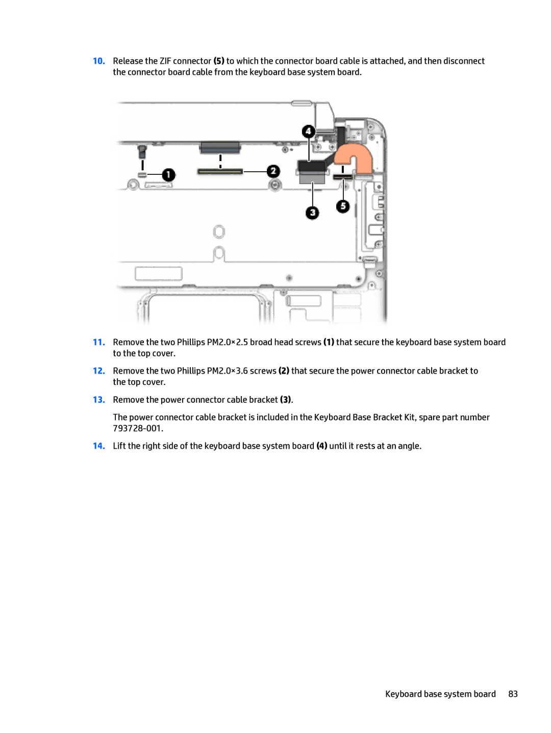
10.Release the ZIF connector (5) to which the connector board cable is attached, and then disconnect the connector board cable from the keyboard base system board.
11.Remove the two Phillips PM2.0×2.5 broad head screws (1) that secure the keyboard base system board to the top cover.
12.Remove the two Phillips PM2.0×3.6 screws (2) that secure the power connector cable bracket to the top cover.
13.Remove the power connector cable bracket (3).
The power connector cable bracket is included in the Keyboard Base Bracket Kit, spare part number
14.Lift the right side of the keyboard base system board (4) until it rests at an angle.
Keyboard base system board 83
