Intel® PXA27x Processor Family Power Requirements
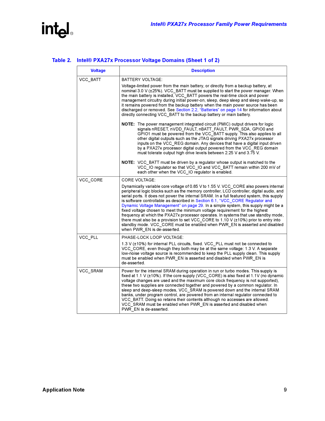
Table 2. Intel® PXA27x Processor Voltage Domains (Sheet 1 of 2)
Voltage | Description |
|
|
VCC_BATT | BATTERY VOLTAGE: |
| |
| nominal 3.0 V (±25%). VCC_BATT must be supplied to start the power manager. When |
| the main battery is installed, VCC_BATT powers the |
| management circuitry during initial |
| it remains powered from the backup battery when the main power source has been |
| discharged or removed. See Section 2.2, “Batteries” on page 14 for information about |
| directly connecting VCC_BATT to the backup battery or main battery. |
| NOTE: The power management integrated circuit (PMIC) output drivers for logic |
| signals nRESET, nVDD_FAULT, nBATT_FAULT, PWR_SDA, GPIO0 and |
| GPIO1 must be powered from the VCC_BATT supply. This also applies to all |
| other digital outputs such as the JTAG signals driving PXA27x processor |
| inputs on the VCC_REG domain. Any devices that have a digital input driven |
| by a PXA27x processor digital output powered from the VCC_REG domain |
| must tolerate output high drive levels between 2.25 V and 3.75 V. |
| NOTE: VCC_BATT must be driven by a regulator whose output is matched to the |
| VCC_IO regulator so that VCC_IO and VCC_BATT remain within 200 mV of |
| each other when the VCC_IO regulator is enabled. |
|
|
VCC_CORE | CORE VOLTAGE: |
| Dynamically variable core voltage of 0.85 V to 1.55 V. VCC_CORE also powers internal |
| peripheral logic blocks such as the memory controller, LCD controller, digital audio, and |
| serial ports. It does not power the internal SRAM. In a full featured system, this supply |
| is software controllable as described in Section 6.1, “VCC_CORE Regulator and |
| Dynamic Voltage Management” on page 29. In a simple system, this supply might be a |
| fixed voltage chosen to meet the minimum voltage requirement for the highest |
| frequency at which the PXA27x processor operates. In systems that use standby mode, |
| there must also be a provision to set VCC_CORE to 1.10 V (±10%) prior to entry into |
| standby mode. VCC_CORE must be enabled when PWR_EN is asserted and disabled |
| when PWR_EN is |
|
|
VCC_PLL |
|
| 1.3 V (±10%) for internal PLL circuits, fixed. VCC_PLL must not be connected to |
| VCC_CORE, even though they both may be at the same voltage: 1.3 V. A separate |
| |
| must be enabled when PWR_EN is asserted and disabled when PWR_EN is |
| |
|
|
VCC_SRAM | Power for the internal SRAM during operation in run or turbo modes. This supply is |
| fixed at 1.1 V (±10%). If the core supply (VCC_CORE) is also fixed at 1.1V (no dynamic |
| voltage changes are used and the maximum core clock frequency is not supported), |
| these two supplies are connected together and powered by a common regulator. In |
| sleep and |
| banks, under program control, are powered from an internal regulator connected to |
| VCC_BATT. Doing so retains their contents although no accesses are allowed. |
| VCC_SRAM must be enabled when PWR_EN is asserted and disabled when |
| PWR_EN is |
|
|
Application Note | 9 |