Intel® PXA27x Processor Family Power Requirements
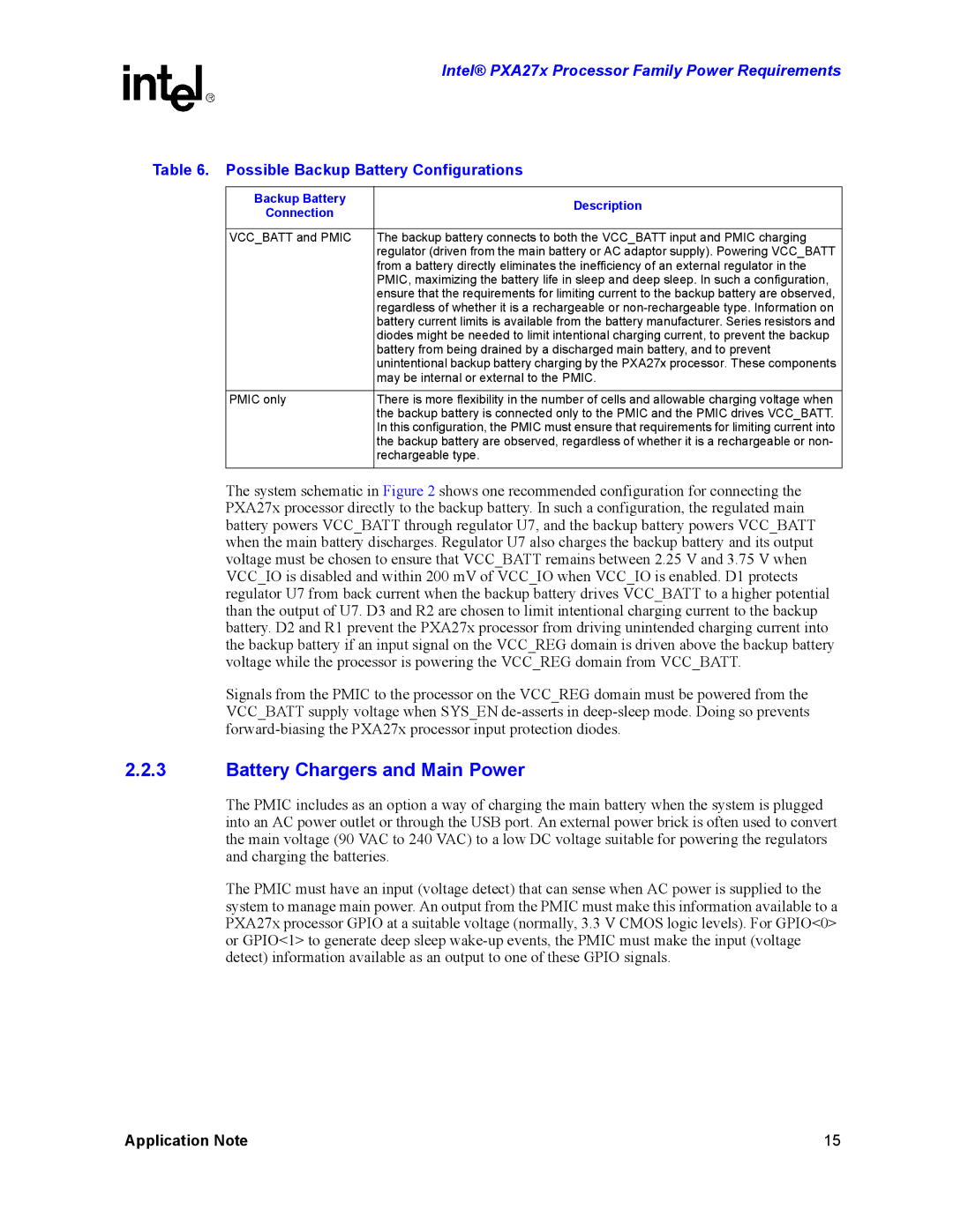
Table 6. Possible Backup Battery Configurations
Backup Battery | Description | |
Connection | ||
| ||
|
| |
VCC_BATT and PMIC | The backup battery connects to both the VCC_BATT input and PMIC charging | |
| regulator (driven from the main battery or AC adaptor supply). Powering VCC_BATT | |
| from a battery directly eliminates the inefficiency of an external regulator in the | |
| PMIC, maximizing the battery life in sleep and deep sleep. In such a configuration, | |
| ensure that the requirements for limiting current to the backup battery are observed, | |
| regardless of whether it is a rechargeable or | |
| battery current limits is available from the battery manufacturer. Series resistors and | |
| diodes might be needed to limit intentional charging current, to prevent the backup | |
| battery from being drained by a discharged main battery, and to prevent | |
| unintentional backup battery charging by the PXA27x processor. These components | |
| may be internal or external to the PMIC. | |
|
| |
PMIC only | There is more flexibility in the number of cells and allowable charging voltage when | |
| the backup battery is connected only to the PMIC and the PMIC drives VCC_BATT. | |
| In this configuration, the PMIC must ensure that requirements for limiting current into | |
| the backup battery are observed, regardless of whether it is a rechargeable or non- | |
| rechargeable type. | |
|
|
The system schematic in Figure 2 shows one recommended configuration for connecting the PXA27x processor directly to the backup battery. In such a configuration, the regulated main battery powers VCC_BATT through regulator U7, and the backup battery powers VCC_BATT when the main battery discharges. Regulator U7 also charges the backup battery and its output voltage must be chosen to ensure that VCC_BATT remains between 2.25 V and 3.75 V when VCC_IO is disabled and within 200 mV of VCC_IO when VCC_IO is enabled. D1 protects regulator U7 from back current when the backup battery drives VCC_BATT to a higher potential than the output of U7. D3 and R2 are chosen to limit intentional charging current to the backup battery. D2 and R1 prevent the PXA27x processor from driving unintended charging current into the backup battery if an input signal on the VCC_REG domain is driven above the backup battery voltage while the processor is powering the VCC_REG domain from VCC_BATT.
Signals from the PMIC to the processor on the VCC_REG domain must be powered from the VCC_BATT supply voltage when SYS_EN
2.2.3Battery Chargers and Main Power
The PMIC includes as an option a way of charging the main battery when the system is plugged into an AC power outlet or through the USB port. An external power brick is often used to convert the main voltage (90 VAC to 240 VAC) to a low DC voltage suitable for powering the regulators and charging the batteries.
The PMIC must have an input (voltage detect) that can sense when AC power is supplied to the system to manage main power. An output from the PMIC must make this information available to a PXA27x processor GPIO at a suitable voltage (normally, 3.3 V CMOS logic levels). For GPIO<0> or GPIO<1> to generate deep sleep
Application Note | 15 |
