Intel® PXA27x Processor Family Power Requirements
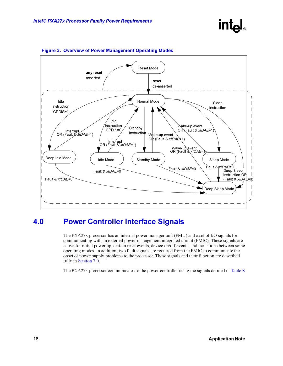
Figure 3. Overview of Power Management Operating Modes
| any reset | Reset Mode |
| ||
|
|
|
| ||
| asserted |
| reset |
| |
|
|
|
| ||
|
|
|
| ||
Idle |
| Normal Mode | Sleep | ||
instruction |
|
|
| ||
|
|
| instruction | ||
CPDIS=1 |
|
|
| ||
|
|
|
| ||
| Idle |
|
|
| |
| instruction | Standby |
| ||
Interrupt | CPDIS=0 | OR (Fault & xIDAE=1) | |||
instruction | |||||
OR (Fault & xIDAE=1) |
| ||||
| Interrupt |
| OR (Fault & xIDAE=1) |
| |
|
|
|
| ||
| OR (Fault & xIDAE=1) |
| |||
|
|
|
| ||
|
|
| OR (Fault & xIDAE=1) | ||
Deep Idle Mode | Idle Mode | Standby Mode | Sleep Mode | ||
| |||||
|
|
| Fault & xIDAE=0 | Fault & xIDAE=0 | |
| Fault & xIDAE=0 |
| Deep Sleep | ||
|
|
| |||
Fault & xIDAE=0 |
|
|
| instruction OR | |
|
|
| (Fault & xIDAE=0) | ||
|
|
|
| Deep Sleep Mode | |
4.0Power Controller Interface Signals
The PXA27x processor has an internal power manager unit (PMU) and a set of I/O signals for communicating with an external power management integrated circuit (PMIC). These signals are active for initial power up, certain reset events, device on/off events, and transitions between some operating modes. In addition, two fault signals are required from the PMIC to communicate the onset of power supply problems to the processor. These signals and their function are described fully in Section 7.0.
The PXA27x processor communicates to the power controller using the signals defined in Table 8.
18 | Application Note |