FS-C8008N FS-C8008DN
Page
Symbols
Regarding Tradenames
Iii
Agfa Monotype License Agreement
FCC statement for users in the United States
Important Notes for Interface connectors
Vii
Viii
Canadian Department of Communications compliance statement
Group for Energy Efficient Appliances Geea
Other Precautions
Installation Precautions
Power Supply/Grounding the Printer
Precautions for Use
Xiv
Description
For More Information
This Operation Guide has the following chapters
This appendix lists the printer’s specifications
Guide to the Operation Guide
Contents
Pagination
Setting Print Quality
Operating the Storage Device
Paper Handling
Index
Ecosys Color FS-C8008DN
Ecosys Color FS-C8008N
Hardware
Features
General
Software
KPDL3 Kyocera Printer Description Language
Networking
Account Management System
Built-in and external network interfaces
Front
Parts and Functions
This tray receives printouts face up
This switch turns printer power on and off
This tray receives printouts face down
Internal
Fuser Unit
Waste Toner Box
Paper Transfer Unit
Primary Transfer Unit
Air is purged through these vents to cool down the inside
Rear
Quick Reference Guide Holder
Hard Disk Slot HDD
Exhaust Duct
Handling Paper
General
Paper specifications
Available paper types
Values
Recommended Paper
Size Product Weight
Minimum and Maximum Paper Sizes
Guidelines
Selecting the Right Paper
Paper conditions
Paper composition
Paper Weight Equivalence Table
Basis weights
Bond Weight lb Europe Metric Weight g/m²
Paper properties
Grain
Moisture content
Thickness Caliper
Other properties of paper
Loading Paper into the Cassette
Loading Paper
Paper size
Use
Loading Paper into the MP Multi-Purpose Tray
Paper type to be used Media type to be selected
Special Paper
Selecting the Special Paper
Adhesive-backed labels
Transparency
Value
Postcards
Colored paper
Envelopes
Pre-printed paper
Recycled paper
Using the Operator Panel
Message Display
Understanding the Operator Panel
Status Information
Message Meaning
Interface Indicator Interface
Indicators in Message Display
Error codes
Paper Size Indicator Size
Indicator Description
Paper Type Indicator Type
READY, DATA, and Attention Indicators
GO Key
Cancel Key
Keys
Arrow Keys
Menu Key
Enter Key
Used. Press the Menu key to return to the Ready display
Menu Selection System
Using the Menu Selection System
Entering the Mode Selection Menu
Paper Handling
Type Adjust
Paper Weight Normal
On the next
Menu System Road Map
Menu Key
USB
ROM
Memory Card Paper Handling Color Mode Monochrome
Buzzer BuzzerOff
Printing a Menu Map
Menu Map and Status Pages
Print Menu Map
Print Menu Map ?
Menu MAP
Print Status
Printing a Status
Print Status Page ?
Prints a status
Hardware Information
Understanding the Status
Software Version
Error Log
Installed Options
Memory
Information
Quick Copy Proof-and-Hold Private Print Stored Job
MPS
Job Retention
Job Storage
Using Quick Copy
Virtual Mailbox
Virtual mailbox can be used in PCL 6 emulation only
Quick Copy Harold
MPS
Quick Copy ?Harold
Quick Copy ?Arlen
Report Delete
Using Proof-and-Hold
Deleting a Quick Copy Job
Press the Enter key. The stored quick copy job is deleted
Private/Stored Harold
Printing a Private Print/Job Retention
Private/Stored ?Harold
Private/Stored ?Arlen
Agenda Copies
Agenda 0000
Agenda Delete
Deleting a Private/Stored Job
Job Manager
Printing a Code Job
Printing a List of Code Jobs
List of Code JOB
List of Code JOB ?
Print VMB Data Tray001
Retrieving Jobs from Virtual Mailbox VMB
Print VMB Data Tray001Richard
Print VMB Data Tray001?Richard
List of VMB ?
List of VMB
Press the U or V key repeatedly until List of VMB appears
Virtual mailboxes as shown in -6below
MPS Configuration
Changing e-MPS Configuration
Quick Copy
Press the Enter key. a blinking cursor appears
Press the Menu key. The display returns to Ready
Temp. Code JOB Size 1550MB
Maximum Space Assigned to Temporary Code Jobs
Appears
Maximum Space Assigned to Permanent Code Jobs
Perm. Code JOB Size 1550MB
Maximum Space Assigned to Virtual Mailboxes VMB
VMB Size 1550MB
Press the Z key Press the U or V key and select VMB Size
Blinking cursor
Changing the Interface Parameters
Changing Parallel Interface Mode
Interface ? Serial
Interface ? Parallel
Press the U or V key repeatedly until Serial appears
Changing Serial Interface Parameters
Range
Baud Rate
Press the Enter key again
Changing Network Interface Parameters
Interface ? Network
EtherTalk Off Network Status Page Off
NetWare
IP Address 000.000.000.00
Resolving IP Address
Off IP Address 000.000.000.000 Subnet Mask Gateway
Network Status Off
Interface Parallel
Status ? Off
Status ? On
Network Status
Emulation ?PCL
Making Default Settings
Default Emulation
KC-GL Pen Width and Color
KC-GL Page Set ? A2
Alternative Emulation for Kpdl Emulation
Alt. Emulation ?PCL
Just selected
Select Kpdl or Kpdl Auto using the U or V key
Printing Kpdl Errors
Emulation ?KPDL
Print Kpdl Errs Off
Font
Default Font
Font Select Internal
?I000
Selecting Regular or Dark Courier/Letter Gothic
Courier Regular
Size Points
Changing the Default Font Size
Character Pitch for Courier/Letter Gothic
Pitch 10.00 cpi
Pitch 10.0 Cpi
Code Set ?IBM PC-8
Setting the Code Set
Code Set IBM PC-8
List of Internal Fonts?
List of Internal Fonts
Printing Lists of Fonts
Fonts are shown in -8on the next
Prescribe
Number of Copies
Pagination
Set
Copies 001
Orientation ? Portrait
Print Orientation
Orientation Portrait
Protect
Protect Mode
Protect ? On
Protect ? Auto
LF Action ? LF only
Linefeed LF Action
LF Action LF only
CR Action ? CR only
Carriage-Return CR Action
CR Action CR only
Tone Mode
Setting Print Quality
Print Quality
Tone Normal
Gloss Mode ? Low
Gloss Mode
Gloss Mode Low
Operating the Storage Device
Using the Memory Card
Memory Card
Read Fonts
Read Fonts Processing
Memory card starts. When completed, Processing disappears
Read Data Report
Read Data ?Report
Write Data ?
Write Data
Writing Data
Memory card write information page as shown below
Partition Type
Deleting Data
Partition Name
Write Partition Length
Delete Data ?Report
Delete Data Report
Format
Format ?
Starts
List of Partitions
Format information page includes the following items
Printing a List of Data Names Partitions
Printout example above includes the following information
List of Partitions ?
Device Name/Number
Partition Size
Using the RAM Disk
Using the Option Hard Disk
RAM Disk Mode ? On
RAM Disk Mode Off
Setting the RAM Disk Size
RAM Disk Size MByte
MP Tray Mode Cassette
MP Tray Mode
MP Tray Mode ? Cassette
Paper Handling
MP Tray Size A4
Setting MP Tray Paper Size
For the MP tray
Through the following paper sizes
MP Tray Type Plain
Setting the MP Tray Paper Type
MP Tray Type ? Plain
Through the following paper types
Cassette 1 Type ? Plain
Setting the Cassette Paper Type
Cassette 1 Type Plain
Feed Select ? Cassette
Selecting the Paper Feed Source
Feed Select Cassette
Binding Modes
Duplex Printing FS-C8008DN
Duplex Mode ?None
Duplex Mode None
None default
Mode is set
Override A4/LT ? Off
Overriding Difference between A4 and Letter
Override A4/LT Off
Type Adjust ? Custom
Type Adjust Custom
Creating Custom Paper Types
Selecting the Custom Type Position
Fuser Mode Low
Paper Weight ? Normal
Fuser Mode ? Low
Selecting the Paper Weight
Duplex Path Enable
Resetting the Custom Paper Type
Duplex Path ? Enable
Step
Reset Type Adjust ?
Reset Type Adjust
Selecting the Output Stack
Stack Select Face-down tray
Selecting the Option Sorter Mode
Collator mode
Mode Description Sorter mode
Mailbox mode
These modes are depicted in -4which follows
Sorter Mode ? Sorter
Sorter Mode
Sorter default
Is changed
Selecting Monochrome or Color Printing
Color Mode
Color Mode ? Color
Displaying the Total Printed Pages
Reading Life Counters
Life Counters
Total Print
New Toner C Installed ?
Resetting the Toner Counter
Selecting the Message Language
Other Modes
Others
MSG Language English
Following order
Automatic Form Feed Timeout Setting
Form Feed Time Out 000sec
Sleep Timer 030 min
Setting the Sleep Timer
Sleep Mode
Sleep Mode ? On
Sleep Timer Timeout Time
Sleep Timer 030min
Print HEX-DUMP
Received Data Dump
Print HEX-DUMP?
Processing Waiting
Printer Reset
Printer Resetting
Printer Reset ?
Self test Please wait Please wait Calibrating Ready
Resouce Prot Off
Resource Protection
Resouce Prot ? Off
Temporary for resource protection
Buzzer ? Off
Alarm Buzzer Setting
Buzzer Off
Auto Continue Mode ? Off
Auto Continue Setting
Auto Continue Mode Off
Auto Continue Timer 030sec
Setting the Auto Continue Recovery Time
Auto Continue Mode On
Finishing Error
Duplex Printing Error Detection Setting
Duplex Off
Duplex ? Off
Service
Printing the Service Status
Color Calibration
When calibration is finished, the display returns to Ready
Color Calibration
Color Calibration ?
Troubleshooting
Tips
Symptom Check Items Corrective Action
General Guidelines
All-black printout
Print Quality Problems
Printed Results Corrective Action Completely blank printout
Ity Tone
Faint or blurred printing
Printing incomplete or out of position
Printed Results Corrective Action Grey background
Dirt on the top edge or back of the paper
Message Corrective Action
Error Messages
Using the Operator Panel, section Formatting a Memory Card
Operator Panel, .10.5 Selecting the Paper Feed Source on
Ing. You can abandon printing by the Cancel key
Yellow, and K Black
Memory Card Errors
Storage Error Codes Hard Disk Errors
RAM Disk Errors
Code Meaning
Possible Paper Jam Locations
Clearing Paper Jams
Duplex unit
PF-30A
Utilizing Online Help Messages
General considerations for clearing jams
Depends on the location of the paper jam
Paper Jam Cassette #
Paper Jam Right Cover #
Paper Jam MP Tray
Paper under the roller
Paper Jam Duplexer
Paper Jam Paper Transfer Unit
Transfer unit, remove the paper
Cover
Open the fuser top cover. Remove the jammed paper
Green-colored lock lever
Paper
On the rear side while removing the paper
Jammed paper
Primary transfer unit
Close the front cover
Paper Jam Left Cover
Fuser unit back into the printer
Open the left cover for the face-up tray
Paper Jam Option Stacker/Finisher/Sorter
That the paper is driven out
Close the left cover. Close the face-up tray
Maintenance
Frequency of toner container replacement
Toner Container Replacement
Starter Toner Containers
Toner Kits
Toner Container Replacement
Replacing the Toner Container
Power off
Container, pull the black toner container out
Damaging media by the magnetism of toner
When it is properly seated
Spilling
Replacing the Waste Toner Box
Place
Cleaning the Paper Transfer Unit
Cleaning the Printer
Clean the registration roller metal using the cleaning cloth
Push the paper transfer unit back in completely
Clean the rubber belts black using the cleaning cloth
Close the front cover
Grid cleaner out of the protective bag and remove the cap
Cleaning the Main Charger Unit
Grid cleaner cannot be reused. Close the front cover
Appendix a Options
Figure A-1
Options
Figure A-2
Expansion Memory Modules
Figure A-3
Installing the Memory Modules
Figure A-5
Memory socket until it clicks in place
Removing a Memory Module
Testing the expanded memory
Memory Card
General Description of Options
Reading Font from the Memory Card
Insert the memory card in the memory card slot
Figure A-9
2 PF-30A Paper Feeder
Figure A-10
3 PD-800 Duplex Unit
5 ST-30 Bulk Stacker
4 SO-30 Sorter
7 CA-31 Casters and CA-31B Caster Kit
6 DF-31 Document Finisher
Figure A-15
Hard Disk
Network interface card Network connections
Installation
9 IB-20/IB-21E/IB-22 Network Interface Cards
Appendix B Computer Interface
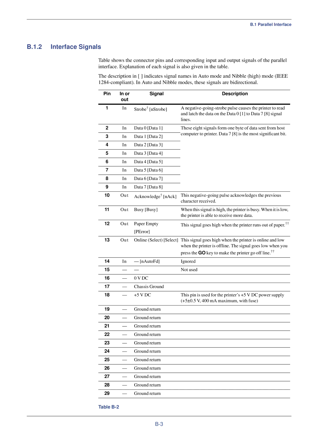
Parallel Interface
Communication Reception Transmission Mode
Communication Modes
You can choose from four communication modes
Pin Signal Description Out
Interface Signals
Table B-2
USB Interface
Specifications
Interface voltage levels
Pin Or out Signal Description
Serial Interface Option
Parameters of the RS-232C Protocol
RS-232C Protocol
H1 Baud rate
H2 Number of data bits
Prescribe Frpo D0 Command
Preparing an RS-232C Cable
Connecting the Printer to the Computer
RS-232C Cable Connection
Double click on Communications Port
Figure B-3
To test the interface, enter the following
DOS, enter the following commands
Appendix C Technical Specifications
Specification
Printer Specification
Inches deep
Printing Speeds
Mode Paper Size Print Speeds Color Monochrome
Index
KPDL3
Prescribe
Kyocera Mita Corporation