OPTIONS
SECTION 10 | OPTIONS | |
|
|
|
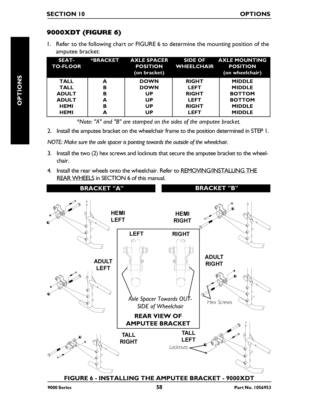
9000XDT (FIGURE 6)
1.Refer to the following chart or FIGURE 6 to determine the mounting position of the amputee bracket:
SEAT- | *BRACKET | AXLE SPACER | SIDE OF | AXLE MOUNTING | |
| POSITION | WHEELCHAIR |
| POSITION | |
|
| (on bracket) |
|
| (on wheelchair) |
|
|
|
|
|
|
TALL | A | DOWN | RIGHT |
| MIDDLE |
TALL | B | DOWN | LEFT |
| MIDDLE |
ADULT | B | UP | RIGHT |
| BOTTOM |
ADULT | A | UP | LEFT |
| BOTTOM |
HEMI | B | UP | RIGHT |
| MIDDLE |
HEMI | A | UP | LEFT |
| MIDDLE |
|
|
|
|
|
|
*Note: "A" and "B" are stamped on the sides of the amputee bracket.
2.Install the amputee bracket on the wheelchair frame to the position determined in STEP 1. NOTE: Make sure the axle spacer is pointing towards the outside of the wheelchair.
3.Install the two (2) hex screws and locknuts that secure the amputee bracket to the wheel- chair.
4.Install the rear wheels onto the wheelchair. Refer to REMOVING/INSTALLING THE REAR WHEELS in SECTION 6 of this manual.
BRACKET "A" | BRACKET "B" | |
HEMI | HEMI | |
LEFT | RIGHT | |
LEFT | RIGHT | |
ADULT | ADULT | |
RIGHT | ||
LEFT | ||
|
Axle Spacer Towards OUT- | Hex Screws | ||
| SIDE of Wheelchair | ||
|
| ||
REAR VIEW OF |
| ||
AMPUTEE BRACKET |
| ||
TALL |
| TALL |
|
| LEFT |
| |
RIGHT |
| ||
Locknuts |
| ||
|
|
| |
FIGURE 6 - INSTALLING THE AMPUTEE BRACKET - 9000XDT
9000 Series | 58 | Part No. 1056953 |