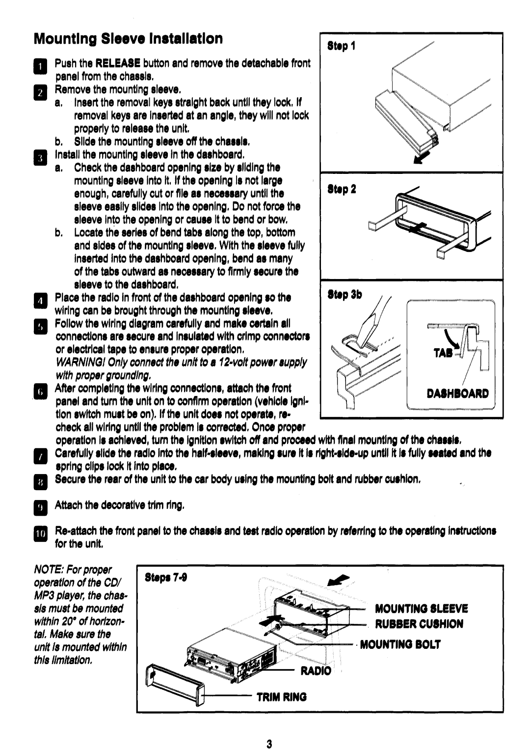
Mounting Sleeve Inltallatlon | StlP 1 | |
a |
| |
Push the RELEASE button and remove the detachable front |
| |
| panel from the chassis. |
|
•Remove the mounting sleeve.
a.Insert the removal keys straight back until they lock. If removal keys are Inserted at an angle, they will not lock properly to release the unit.
b.Slide the mounting sleeve off the chassis.
•Install the mounting sleeve In the dashboard.
a.Check the dashboard opening size by sliding the
| mounting sleeve Into It. If the opening Is not large | Stlp2 | ||
| enough, carefully cut or file as necessary until the | |||
|
|
|
| |
| sleeve easily slides Into the opening. Do not force the |
|
|
|
| sleeve Into the opening or cause It to bend or bow, |
|
|
|
| b. Locate the series of bend tabs along the top, bottom |
|
|
|
| and sides of the mounting sleeve. With the sleeve fully |
|
|
|
| Inserted Into the dashboard opening, bend as many |
|
|
|
| of the tabs outward as necessary to firmly secure the |
|
|
|
II | sleeve to the dashboard. | Stlp 3b |
|
|
Place the radio In front of the dashboard op.nlng so the |
|
| ||
| ||||
| wiring can be brought through the mounting sl•• ve, |
|
|
|
•Follow the wiring diagram carefully and make certain all connections are secure and Insulated with crimp conn.ctor. or electrical tape to ensure prop.r op.ratlon, WARNINGI Only connect the unit to a
• | After completing the wiring connections, attach the front |
| DAlHIOARD | |
. | pan.'and turn the unit on to confirm op.ratlon (v.hlcl. Igni- |
| ||
| tion switch mu.t b. on). If the unit doe. not op.rate, r.- |
|
|
|
|
|
|
| |
| check all wiring until the problem I. corrected, Once prop.r |
|
|
|
operation I. achieved, tum the Ignition switch oft and proce.d with final mounting of the cha•• '••
•Carefully .lId. the radio Into the
.prlng clip. lock It Into place,
•Secure the rear of the unit to the car body u.'ngthe mountIng bolt and rubber cu.hlon,
•Attach the decorative trim ring.
II
NOTE: For proper operation of the COl MP3 player, the chas- sis must be mounted within 20· of horizon- tal, Make sure the unit Is mounted within this limitation,
MOUNTING SLEEVE
\~~~,
,....;.......,...."".
'~<~J
+
3