Wiring Diagram
IMPORTANT Incorrect wiring connections can damage the unit. Follow the wiring instructions carefully, or have the installation handled by an experienced technician.
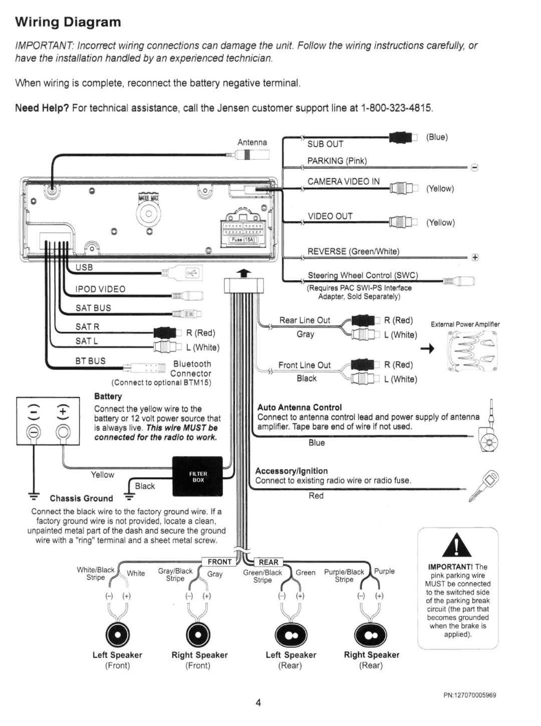
When wiring is complete, reconnect the battery negative terminal.
Need Help? For technical assistance, call the Jensen customer support line at
Antenna
(Blue)
SUB OUT
PARKINGe
0
0@)
0 0
~
~
IPODVIDEO
| R (Red ) |
| L (White) |
BT BUS | .. .~ Bluetooth |
| • ••J).. Connector |
| (Connect 10 optional BTM15 ) |
CAMERA VIDEO IN
(Yellow)
VIDEO OUT
(Yellow)
REVERSE
$
Wheel Control
(Requires PAC
Adapter, Sold Separately)
Rear Line Out | R (Red ) |
Gray | L (White) |
Front Line Out | |
| |
Black | L (White) |
|
| Battery | |
- | + | ||
Connect the yellow wire to the | |||
battery or 12 volt power source that | |||
- | |||
- | - | Is always live. This wire MUST be | |
|
| connected for the radio to work. |
Yellow
Chassis Ground
Connect the black wire to the factory ground wire . If a factory ground wire is not provided, locate a clean, unpainted metal part of the dash and secure the ground wire with a "ring" terminal and a sheet metal screw.
Auto Antenna Control~ Connect to antenna control lead and power supply of antenna
amplifier. Tape bare end of wire If not used.
Accessoryllgnltlon@
~c_o_n_n_ect_to__eXi~st~n~g_ra_dio wire or_r_a_di_O_fu_s_e.__________ ~
A
White/Black | Gray/Black | Green/Black | Purple/Black |
Stripe | Stripe | Stripe | Stripe |
|
| (- ) (+) | |
0 | 0 | 0 | V |
|
IMPORTANTI The
pink parking wire
MUST be connected to the switched side of the parking break circuit (the part that
becomes grounded when the brake is
0 |
l
applied). j
Left Speaker | Right Speaker | Left Speaker | Right Speaker |
(Front) | (Front) | (Rear) | (Rear) |
PN:127070005969
4