Chapter 2: VLANs
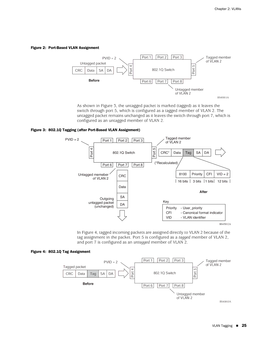
Figure 2: Port-Based VLAN Assignment
|
| PVID = 2 |
|
| ||
Untagged packet |
|
| ||||
|
|
|
|
| 4 |
|
CRC | Data | SA | DA |
| Port |
|
|
|
| ||||
|
|
|
|
|
|
|
|
|
|
|
|
|
|
Before
Port 1 |
| Port 2 |
| Port 3 |
|
| Tagged member |
|
|
|
|
|
|
| of VLAN 2 |
|
|
|
|
|
| 5 |
|
| 802.1Q Switch |
| Port |
| |||
|
|
|
| ||||
|
|
|
|
|
|
|
|
|
|
|
|
|
|
|
|
Port 6 |
| Port 7 |
| Port 8 |
|
|
|
Untagged member of VLAN 2
BS45011A
As shown in Figure 3, the untagged packet is marked (tagged) as it leaves the switch through port 5, which is configured as a tagged member of VLAN 2. The untagged packet remains unchanged as it leaves the switch through port 7, which is configured as an untagged member of VLAN 2.
Figure 3: 802.1Q Tagging (after Port-Based VLAN Assignment)
PVID = 2 |
|
| Port 1 |
| Port 2 |
| Port 3 |
|
|
|
|
|
|
| |||
|
|
|
|
|
|
|
|
|
| 4 |
|
|
|
|
|
|
|
| Port |
|
| 802.1Q Switch | ||||
|
|
|
| |||||
|
|
|
|
|
|
|
|
|
|
|
|
|
|
|
|
|
|
|
|
| Port 6 |
| Port 7 |
| Port 8 |
|
Untagged memeber | CRC | |
of VLAN 2 | ||
| ||
| Data | |
Outgoing | SA | |
| ||
untagged packet | DA | |
(unchanged) | ||
|
Tagged member of VLAN 2
5 |
|
|
|
|
|
|
|
|
|
|
|
|
|
|
|
|
|
|
Port |
| CRC* | Data | Tag | SA |
| DA |
|
|
|
|
|
| |||||
|
|
|
|
|
|
|
|
| ||||||||||
|
|
|
|
|
|
|
|
|
|
|
|
|
|
|
|
|
| |
|
|
|
|
|
|
|
|
|
|
|
|
|
|
|
|
|
|
|
(*Recalculated) |
|
|
|
|
|
|
|
|
|
|
| |||||||
|
|
|
|
|
|
|
|
|
|
|
|
|
|
| ||||
|
|
|
|
|
| 8100 |
| Priority |
| CFI |
| VID = 2 |
| |||||
|
|
|
|
|
|
|
|
|
|
|
|
|
|
| ||||
|
|
|
|
|
| 16 bits |
| 3 bits |
| 1 bits |
| 12 bits |
|
| ||||
|
|
|
|
|
|
|
|
|
| |||||||||
|
|
|
|
|
|
|
|
|
| After |
|
|
|
|
| |||
|
|
| Key |
|
|
|
|
|
|
|
|
|
|
|
|
| ||
|
|
|
|
|
|
|
|
|
|
|
|
|
|
|
|
|
| |
|
|
| Priority | - User_priority |
|
|
|
|
|
|
|
| ||||||
|
|
| CFI | - Canonical format indicator |
|
|
| |||||||||||
|
|
| VID | - VLAN identifier |
|
|
|
|
| |||||||||
|
|
|
|
|
|
|
|
|
|
|
|
|
|
|
|
|
|
|
BS45012A
In Figure 4, tagged incoming packets are assigned directly to VLAN 2 because of the tag assignment in the packet. Port 5 is configured as a tagged member of VLAN 2, and port 7 is configured as an untagged member of VLAN 2.
Figure 4: 802.1Q Tag Assignment
Tagged packet
CRC Data ![]() Tag
Tag
Before
PVID = 2 |
| ||
| |||
|
|
|
|
|
|
| 4 |
SA | DA |
| Port |
|
| ||
|
|
|
|
|
|
|
|
|
|
|
|
Port 1 |
| Port 2 |
| Port 3 |
|
| Tagged member |
|
|
|
|
|
|
| of VLAN 2 |
|
|
|
|
|
| 5 |
|
| 802.1Q Switch | Port |
| ||||
|
|
| |||||
|
|
|
|
|
|
|
|
|
|
|
|
|
|
|
|
Port 6 |
| Port 7 |
| Port 8 |
|
|
|
Untagged member of VLAN 2
BS45013A
VLAN Tagging 25