Chapter 3: Spanning Tree Protocol
Per VLAN Rapid Spanning Tree
Per VLAN Rapid Spanning Tree Plus Protocol (PVRST+) enhances the RSTP protocol by adding the ability to have multiple Spanning Tree Groups (STGs). PVRST+ is based on IEEE 802.1w Rapid Spanning Tree Protocol.
In PVRST mode, the EX2500 switch supports a maximum of 128 Spanning Tree Groups (STGs). Multiple STGs provide multiple data paths, which can be used for load balancing and redundancy.
To enable load balancing between two EX2500 switches using multiple STGs, configure each path with a different VLAN and then assign each VLAN to a separate STG. Each STG is independent. Each STG sends its own Bridge Protocol Data Units (BPDUs), and each STG must be configured independently.
The STG, or bridge group, forms a
Default Spanning Tree Configuration
In the default configuration, a single STG (STG 1) includes all
All other STGs, except the default STG 1, are empty and you must assign a VLAN to the STG. However, you cannot assign ports directly to an STG. Instead, you add ports to a VLAN and add the VLAN to the STG. Each STG is enabled by default, and assigned an ID number from 2 to 128.
By default, the spanning tree on the management port is turned off.
Why Do We Need Multiple Spanning Trees?
The following examples describe why we need multiple spanning trees.
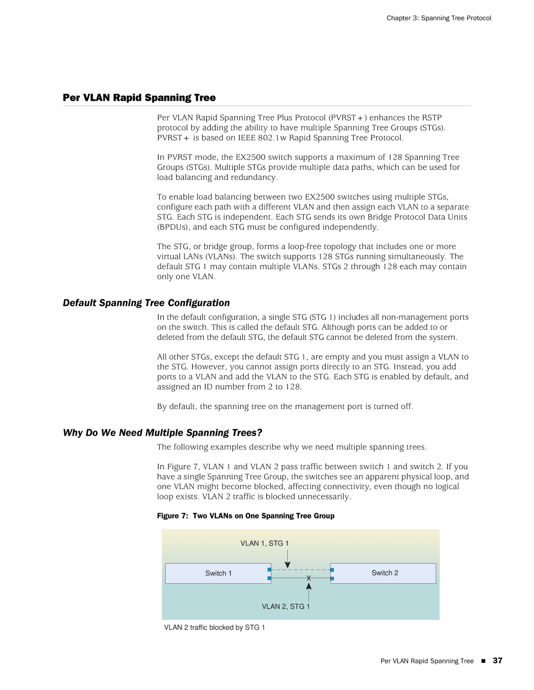
In Figure 7, VLAN 1 and VLAN 2 pass traffic between switch 1 and switch 2. If you have a single Spanning Tree Group, the switches see an apparent physical loop, and one VLAN might become blocked, affecting connectivity, even though no logical loop exists. VLAN 2 traffic is blocked unnecessarily.
Figure 7: Two VLANs on One Spanning Tree Group
| VLAN 1, STG 1 |
| ||
|
|
|
|
|
Switch 1 |
|
| X | Switch 2 |
|
| |||
|
| |||
|
|
|
| |
|
|
|
|
|
VLAN 2, STG 1
VLAN 2 traffic blocked by STG 1
Per VLAN Rapid Spanning Tree 37