2. CONTROLS, INDICATORS AND CONNECTORS
2-5 Adapter Section (continued)
PUSH
7
| VTR/RM | DV | CAMCORDER |
| |||
|
| ||
8 |
|
|
|
| PROMPTER |
|
|
| OUTPUT |
|
|
9 |
|
| GENLOCK/AUX IN |
Y/C OUT MONITOR OUT | LINE OUT | VIDEO OUT | |
|
| ||
|
|
| REMOTE |
|
|
| AUDIO IN |
|
|
| FRONT |
| TC IN | TC OUT | LENS |
|
|
| |
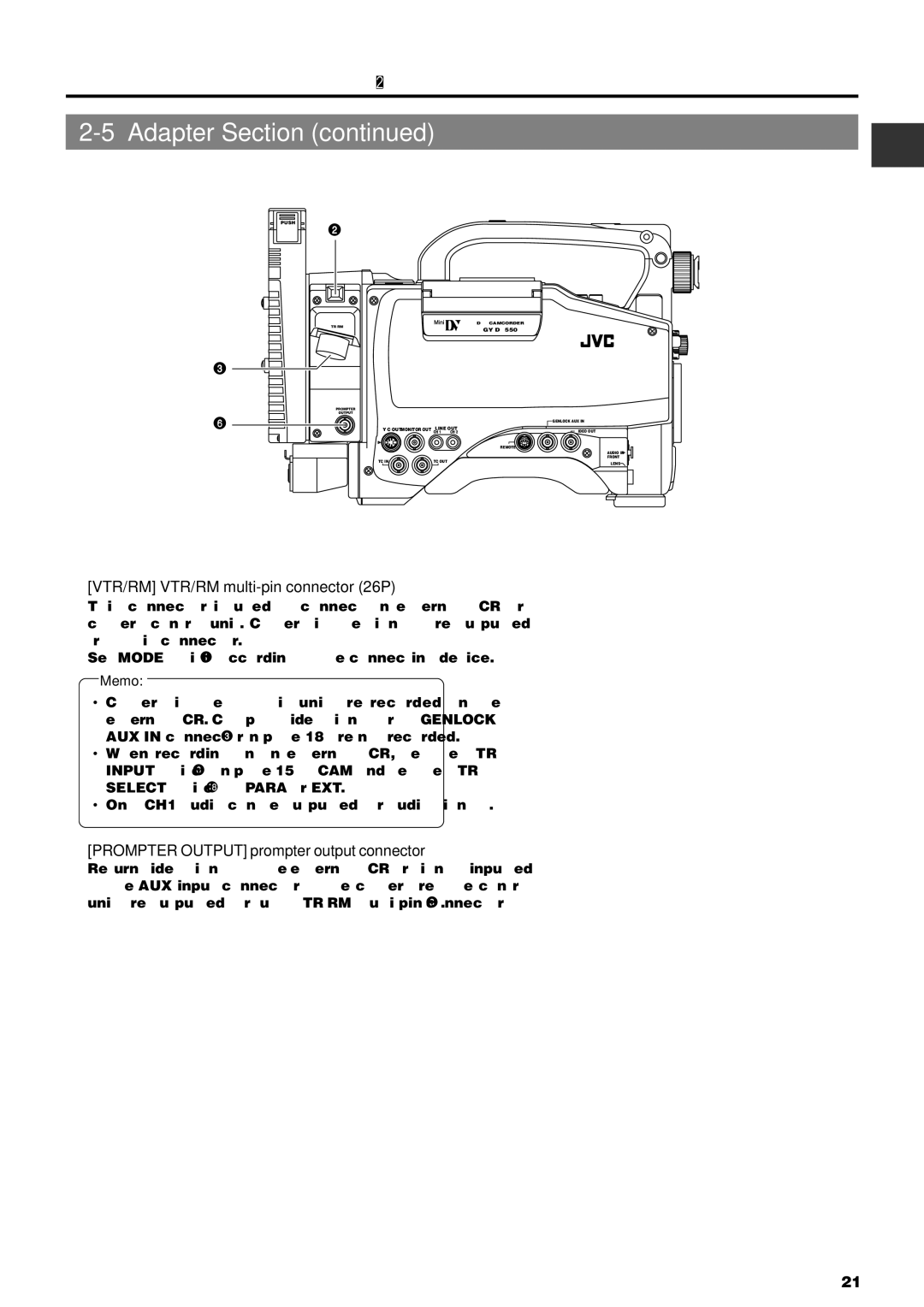
8[VTR/RM] VTR/RM multi-pin connector (26P)
This connector is used to connect an external VCR or camera control unit. Camera image signals are outputted from this connector.
Set MODE switch 6 according to the connecting device.
Memo:
•Camera images of this unit are recorded on the external VCR. Compost video signals from GENLOCK/ AUX IN connector 8 on page 18 are not recorded.
•When recording on an external VCR, set the VTR INPUT switch 9 on page 15 to CAM and set the VTR SELECT switch = to PARA or EXT.
•Only CH1 audio can be outputted for audio signals.
9[PROMPTER OUTPUT] prompter output connector
Return video signals of the external VCR or signals inputted to the AUX input connector of the camera remote control unit are outputted through VTR/RM
21