INSTALLING
 YOUR
YOUR
 NEW
NEW
 RECORD
 ER
ER


![]()
![]()
![]()
![]()
![]()
![]()
![]()
![]()
![]()
![]()
![]()
![]()
![]() EN
EN![]()
![]() 3
3![]()
Basic Connections
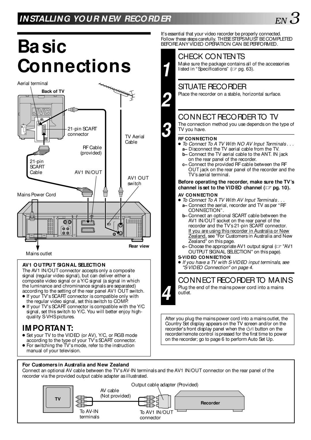
Aerial terminal
Back of TV
|
| |
| connector | TV Aerial |
|
| |
| RF Cable | Cable |
|
| |
| (provided) |
|
|
| |
SCART | AV1 IN/OUT |
|
Cable |
| |
|
| AV1 OUT |
|
| switch |
Mains Power Cord |
|
|
Rear view
Mains outlet
AV1 OUTPUT SIGNAL SELECTION
The AV1 IN/OUT connector accepts only a composite signal (regular video signal), but can deliver either a composite video signal or a Y/C signal (a signal in which the luminance and chrominance signals are separated) according to the setting of the rear panel AV1 OUT switch.
●If your TV's SCART connector is compatible only with the regular video signal, set this switch to COMP.
●If your TV's SCART connector is compatible with the Y/C signal, set this switch to Y/C. You will better enjoy high- quality
IMPORTANT:
●Set your TV to the VIDEO (or AV), Y/C, or RGB mode according to the type of your TV's SCART connector.
●For switching the TV's mode, refer to the instruction manual of your television.
It's essential that your video recorder be properly connected. Follow these steps carefully. THESE STEPS MUST BE COMPLETED BEFORE ANY VIDEO OPERATION CAN BE PERFORMED.
| CHECK CONTENTS |
| Make sure the package contains all of the accessories |
1 listed in “Specifications” (☞ pg. 63). | |
| SITUATE RECORDER |
2 Place the recorder on a stable, horizontal surface. | |
3 | CONNECT RECORDER TO TV |
The connection method you use depends on the type of | |
TV you have. | |
| |
RF CONNECTION | |
| ● To Connect To A TV With NO AV Input Terminals . . . |
| a– Disconnect the TV aerial cable from the TV. |
| b– Connect the TV aerial cable to the ANT. IN jack |
| on the rear panel of the recorder. |
| c– Connect the provided RF cable between the RF |
| OUT jack on the rear panel of the recorder and the |
| TV’s aerial terminal. |
| Before operating the recorder, make sure the TV’s |
| channel is set to the VIDEO channel (☞ pg. 10). |
AV CONNECTION
●To Connect To A TV With AV Input Terminals . . .
a– Connect the aerial, recorder and TV as per “RF
CONNECTION”.
b– Connect an optional SCART cable between the AV1 IN/OUT socket on the rear panel of the recorder and the TV’s
Zealand" on this page.
c– Choose the appropriate AV1 output signal (☞ "AV1
OUTPUT SIGNAL SELECTION" on this page).
●If you have a TV with
CONNECT RECORDER TO MAINS
4 Plug the end of the mains power cord into a mains outlet.
After you plug the mains power cord into a mains outlet, the Country Set display appears on the TV screen and/or on the
recorder's front display panel when the ![]()
![]()
![]() button on the recorder/remote control is pressed for the first time to power on the recorder; go to page 6 to perform Auto Set Up.
button on the recorder/remote control is pressed for the first time to power on the recorder; go to page 6 to perform Auto Set Up.
For Customers in Australia and New Zealand
Connect an optional AV cable between the TV's
TV
Output cable adapter (Provided)
AV cable
(Not provided)
Recorder
To | To AV1 IN/OUT |
terminals | connector |