HV- 29LPZ
ADJUSTMENT
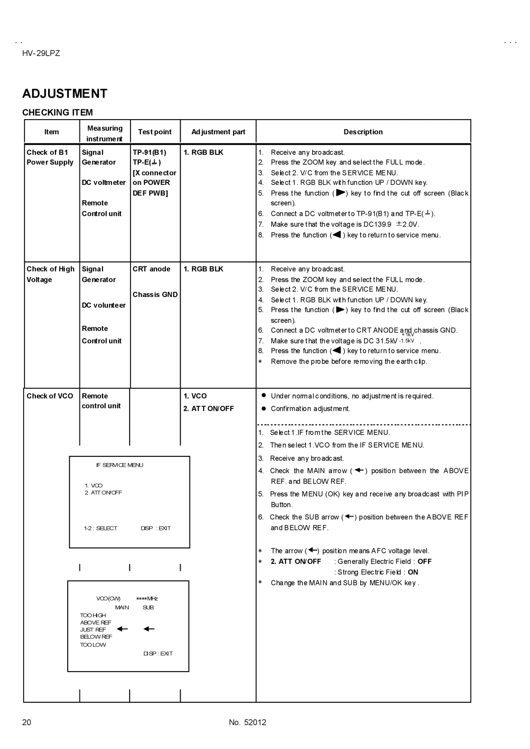
CHECKING ITEM
Item
Measuring | Test point | Adjustment part | |
instrument | |||
|
|
Description
| Check of B1 |
| Signal | 1. RGB BLK | 1. | Receive any broadcast. |
|
|
| ||||||||||
| Power Supply |
| Generator |
|
|
| 2. | Press the ZOOM key and select the FULL mode. | |||||||||||
|
|
|
|
|
|
| [X connector |
|
|
| 3. | Select 2. V/C from the SERVICE MENU. | |||||||
|
|
|
|
|
| DC voltmeter | on POWER |
|
|
| 4. | Select 1. RGB BLK with function UP / DOWN key. | |||||||
|
|
|
|
|
|
| DEF PWB] |
|
|
| 5. | Press the function ( | ) key to find the cut off screen (Black | ||||||
|
|
|
|
|
| Remote |
|
|
|
|
| screen). |
|
|
|
|
| ||
|
|
|
|
|
| Control unit |
|
|
|
| 6. | Connect a DC voltmeter to | |||||||
|
|
|
|
|
|
|
|
|
|
| 7. | Make sure that the voltage is DC139.9 ±2.0V. | |||||||
|
|
|
|
|
|
|
|
|
|
| 8. | Press the function ( | ) key to return to service menu. | ||||||
|
|
|
|
|
|
|
|
|
|
|
|
|
|
|
|
|
|
| |
| Check of High |
| Signal | CRT anode | 1. RGB BLK | 1. | Receive any broadcast. |
|
|
| |||||||||
| Voltage |
| Generator |
|
|
|
| 2. | Press the ZOOM key and select the FULL mode. | ||||||||||
|
|
|
|
|
|
| Chassis GND |
|
|
| 3. | Select 2. V/C from the SERVICE MENU. | |||||||
|
|
|
|
|
|
|
|
|
| 4. | Select 1. RGB BLK with function UP / DOWN key. | ||||||||
|
|
|
|
|
| DC volunteer |
|
|
|
| |||||||||
|
|
|
|
|
|
|
|
|
| 5. | Press the function ( | ) key to find the cut off screen (Black | |||||||
|
|
|
|
|
|
|
|
|
|
| |||||||||
|
|
|
|
|
|
|
|
|
|
|
| screen). |
|
|
|
|
| ||
|
|
|
|
|
| Remote |
|
|
|
| 6. | Connect a DC voltmeter to CRT ANODE and chassis GND. | |||||||
|
|
|
|
|
|
|
|
|
|
|
|
|
|
|
|
|
|
| +1kV |
|
|
|
|
|
| Control unit |
|
|
|
| 7. | Make sure that the voltage is DC 31.5kV | |||||||
|
|
|
|
|
|
|
|
|
|
| 8. | Press the function ( | ) key to return to service menu. | ||||||
|
|
|
|
|
|
|
|
|
|
| * | Remove the probe before removing the earth clip. | |||||||
|
|
|
|
|
|
|
|
|
|
|
|
|
|
|
|
| |||
| Check of VCO |
| Remote |
| 1. VCO | " Under normal conditions, no adjustment is required. | |||||||||||||
|
|
|
|
|
| control unit |
| 2. ATT ON/OFF | " | Confirmation adjustment. |
|
|
| ||||||
|
|
|
|
|
|
|
|
|
|
| |||||||||
|
|
|
|
|
|
|
|
|
|
| 1. | Select 1.IF from the SERVICE MENU. | |||||||
|
|
|
|
|
|
|
|
|
|
| 2. | Then select 1.VCO from the IF SERVICE MENU. | |||||||
|
|
|
|
|
|
|
|
|
|
| |||||||||
|
|
|
|
|
|
|
|
|
|
| 3. | Receive any broadcast. |
|
|
| ||||
|
|
|
|
|
| IF SERVICE MENU |
|
|
|
|
|
| |||||||
|
|
|
|
|
|
|
|
| 4. | Check the MAIN arrow ( |
|
| ) position between the ABOVE | ||||||
|
|
|
|
|
|
|
|
|
|
|
|
| |||||||
|
|
|
|
|
|
|
|
|
|
|
|
| |||||||
|
|
|
|
|
| 1. VCO |
|
|
|
|
| REF. and BELOW REF. |
|
|
| ||||
|
|
|
|
|
|
|
|
|
|
|
|
|
|
|
|
|
|
| |
|
|
|
|
|
| 2. ATT ON/OFF |
|
|
|
| 5. | Press the MENU (OK) key and receive any broadcast with PIP | |||||||
|
|
|
|
|
|
|
|
|
|
|
| Button. |
|
|
|
|
| ||
|
|
|
|
|
|
|
|
|
|
| 6. | Check the SUB arrow ( |
| ) position between the ABOVE REF | |||||
|
|
|
|
|
|
|
|
|
|
|
| ||||||||
|
|
|
|
|
| DISP : EXIT |
|
|
|
| and BELOW REF. |
|
|
|
|
| |||
|
|
|
|
|
|
|
|
|
|
| * | The arrow ( |
| ) position means AFC voltage level. | |||||
|
|
|
|
|
|
|
|
|
|
| |||||||||
|
|
|
|
|
|
|
|
|
|
|
| ||||||||
|
|
|
|
|
|
|
|
|
|
| * | 2. ATT ON/OFF : Generally Electric Field : OFF | |||||||
|
|
|
|
|
|
|
|
|
|
| * |
|
| : Strong Electric Field : ON | |||||
|
|
|
|
|
|
|
|
|
|
| |||||||||
|
|
|
|
|
|
|
|
|
|
| Change the MAIN and SUB by MENU/OK key . | ||||||||
|
|
|
|
|
|
|
|
|
|
| |||||||||
VCO(CW) ****MHz
MAIN SUB
TOO HIGH
ABOVE REF
JUST REF
BELOW REF
TOO LOW
DISP : EXIT
20 | No. 52012 |