Instructions
CD Receiver
How to use the Mode button
How to reset your unit
How to forcibly eject a disc
For safety
Contents
Parts identification
Display window
Main elements and features
Installing the lithium coin battery CR2025
To drop the volume in a moment ATT
Basic settings
To turn off the power
Basic operations
To tune in to a station manually
When an FM stereo broadcast is hard to receive
Storing stations in memory
Clock =Station name
Playing a disc in the unit
Manual presetting
Listening to a preset station
Playing discs in the CD changer
About the CD changer
Playing from a USB memory
About MP3 and WMA tracks
To go to the next or previous tracks
Prohibiting disc ejection
Other main functions
To go to the next or previous folders only for MP3/WMA/USB
Selecting the playback modes
USB memory
Changing the display information
While playing an MP3/WMA*2 disc or
Indication For
Adjusting the sound
Indication Range
General settings PSM
Indications Selectable settings, reference
LOW PWR
To erase the entire title
Sources
For iPod
Selecting a track from the menu
Preparations
Genres Ôcomposer Ôback to the beginning For D. player
Confirm the selection
Tuner operations
Disc operations
Playing a CD-R or CD-RW
Playing a disc
Playing an MP3/WMA disc
Changing the source
General settings-PSM
Title assignment
Ejecting a disc
To keep discs clean
How to clean the connectors
How to handle discs
Moisture condensation
Troubleshooting
Symptoms Remedies/Causes
On the next
Symptoms Remedies/Causes
CD changer IPod/D. player playback
FM Tuner
AM Tuner
Having Trouble with operation?
�4 Ω 8 Ω
Precautions on power supply and speaker connections
Parts list for installation and connection
Will be seriously damaged
Removing the unit
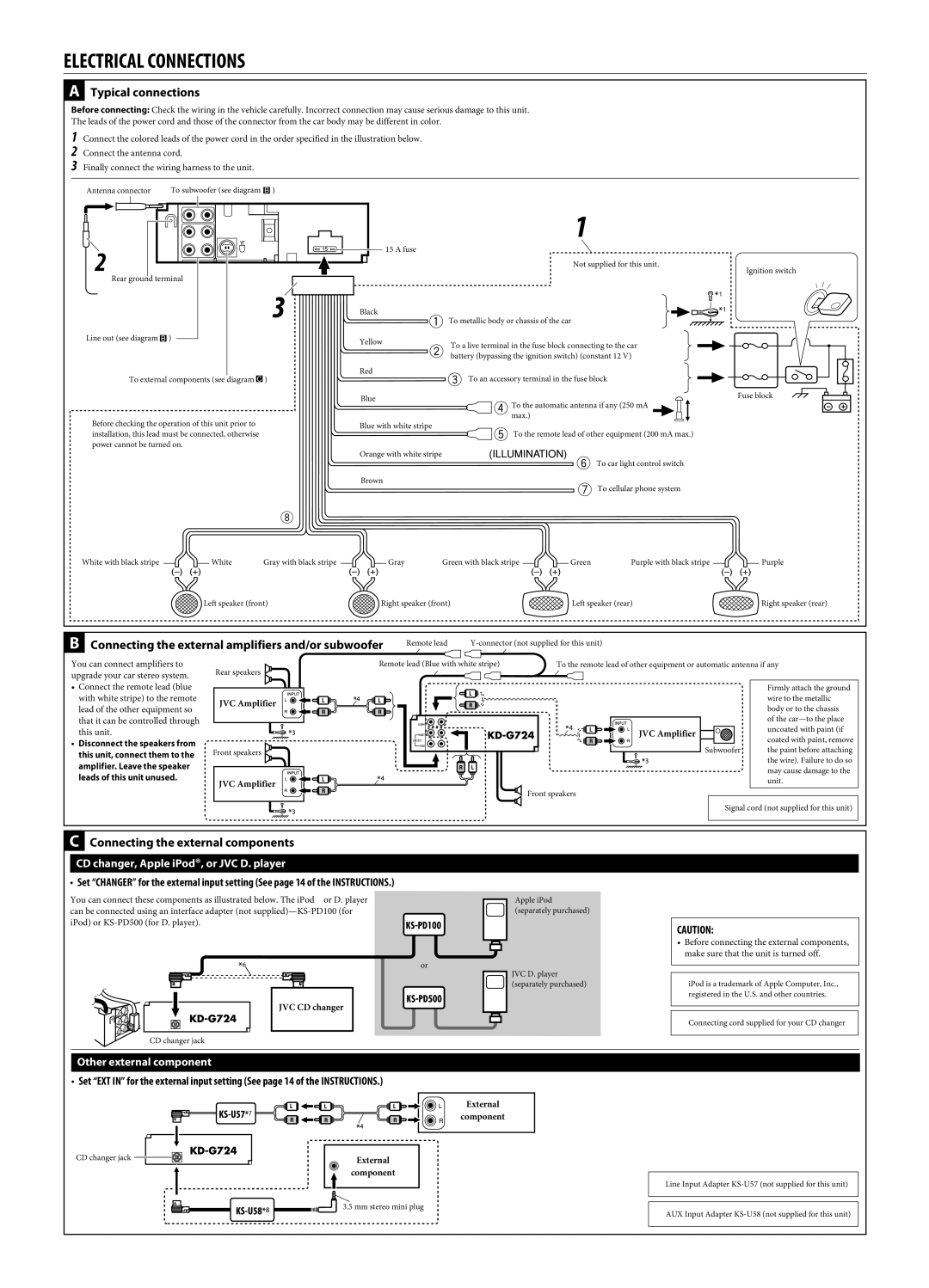
Electrical Connections
Typical connections
�14
Connecting the external amplifiers and/or subwoofer
Connecting the external components
Leads of this unit unused
Information For U.S.A
Important for Laser Products
English
Control panel KD-AR770 and KD-G720
Remote controller RM-RK50
Display window
Returns to the previous menu ∞ Confirms the selection
To drop the volume in a moment ATT
Basic operations
See also General settings PSM on pages
To check other information while listening to the radio
Listening to a preset station
Clock = Station name* = Frequency = back to the beginning
Playing a disc in the unit
Playing from a USB memory
Playing discs in the CD changer
To fast-forward or reverse the track
To go to the next or previous tracks
While playing an MP3/WMA*2 disc or a
TRK RPT
Indication, Range
Loud OFF
SCROLL*5 Once
OFF*1
Ex. When CD is selected as the source
Activate your Sirius subscription after connection
Listening to the satellite radio
Activate your XM subscription after connection
Searching for category/channel
Listening to the XM Satellite radio
Listening to the Sirius Satellite radio
Storing channels in memory
Listening to a preset channel
Checking the XM Satellite radio ID
To pause*1 or stop*2 playback
To go to the next or previous tracks
Selecting the playback modes
Selecting a track from the menu
Other external component operations
Basic operations
Inserting a disc
General settings-PSM
Title assignment
IPod or D. player operations
FM/AM General Disc playback MP3/WMA playback
MP3/WMA playback USB memory playback
Radio
Satellite radio IPod/D. player playback
FM Tuner
AM Tuner
Call
Liste des pièces pour l’installation et raccordement
Remarques
Unit becomes hot
Antes de extraer la unidad, libere la sección trasera
Nota
El fusible se quema
Conexiones Electricas
Amplifier. Leave the speaker leads of this unit unused
JVC DLP
GET0355-001A
How to reset your unit
Contents
Control panel
Remote controller RM-RK50
Getting started
Radio operations
Disc/USB memory operations
Playing from a USB memory
Other main functions
USB memory
Sound adjustments
General settings PSM
Indications Selectable settings, reference
Title assignment
IPod/D. player operations
Selecting the playback modes
Operations
Playing a disc
Title assignment
Maintenance
Disc
On the next
Symptoms Remedies/Causes
Specifications
EN, TH
§‡µÕπ
When using the optional stay / ‡¡ËՄȵ«¬÷- ¥·‡≈Õ‰¥È
√µ‘¥µßÈ- √ª√-Õ·ºßÀπȪ∑¡Ï‡- ¢È
√‡ËÕ¡‚¥¬„ȉøøÈ
Typical connections / √‡ËÕ¡µËÕ·ªµ
´«Ÿ‡øÕ√
Instructions Buku Petunjuk
English
Contents
Control panel
Remote controller RM-RK50
Getting started
Radio operations
Disc/USB memory operations
Playing from a USB memory
Other main functions
USB memory
Sound adjustments
General settings PSM
Indications Selectable settings, reference
Title assignment
IPod/D. player operations
Selecting the playback modes
Operations
Playing a disc
Title assignment
Maintenance
Troubleshooting
On the next
Symptoms Remedies/Causes
Specifications
Ada Masalah dengan cara Pengoperasian?
Peringatan
Memindahkan alat penerima
SAMBUNGAN-SAMBUNGAN Listrik
Typical connections / Ciri khas sambungan-sambungan
Other external component / Komponen eksternal lainnya
KD-G724
How to reset your unit
Contents
Control panel
Remote controller RM-RK50
Getting started
Radio operations
Playing discs in the CD changer
Playing from a USB memory
Other main functions
While playing an audio CD or a CD Text
BAS TRE
Adjust the PSM item selected
Indications Selectable settings, reference
Move to the next or previous character position
IPod/D. player operations
Selecting the playback modes
Tuner operations Storing stations in memory
Basic operations Turning on the power
Disc operations
Playing a disc
General settings-PSM
Maintenance
Troubleshooting
On the next
Symptoms
CD PLAYER/USB Memory Section
Having Trouble with operation?
When using the optional stay
KD-G724
CD changer, Apple iPod, or JVC D. player
KD-G722/KD-G721
English
Radio operations FM RDS operations
Control panel KD-G722 and KD-G721
Remote controller RM-RK50
CR2025 or its equivalent otherwise, it may
To drop the volume in a Moment ATT
Selected band appears
What you can do with RDS
Searching for your favorite FM RDS programme
Frequency ÔClock
TA Standby Reception
Using the standby receptions
Types
PTY Standby Reception
Network-Tracking Reception
Tracing the same programme
Playing from a USB memory
English
Skipping tracks quickly during play
MP3-compatible CD changer
English
BAS TRE Loud
AF REG
TA VOL
TAG Disp TAG on
Selecting a track from the menu
Albm RND
To tune in to an ensemble manually
Storing DAB services in memory
What is DAB system?
EXT in ÔClock
Tuning in to a preset DAB service
Tracing the same programme- Alternative Frequency Reception
FM RDS operations
Disc operations
Playing MP3/WMA tracks from a USB memory
DAB tuner operations
IPod or D. player operations
FM/AM General Disc playback
MP3/WMA playback Playback
CD changer IPod/D. player playback
MW Tuner
LW Tuner
Vous avez des Problèmes de Fonctionnement?
KD-G722/KD-G721
Installation Montage Dans LE Tableau DE Bord
Remarque
Electrical Connections Raccordements Electriques
Other external component / Autre appareil extérieur
Руcckий Deutsch English
English
Contents
Parts identification
Remote controller RM-RK50
Main elements and features
Getting started
Radio operations
FM RDS operations
Types
Disc/USB memory
Playing from a USB memory
Other main functions
English
Sound adjustments
General settings PSM
TA VOL
Title assignment
IPod/D. player operations
Other external component operations
DAB tuner operations
More about this unit
English
Changing the source
Maintenance
Troubleshooting
MP3/WMA playback Playback
DAB
Specifications
Обратитесь на соответствующую страницу
Для получения информации о перезагрузке Вашего устройства
Precautions on power supply and speaker
Removing the unit Ausbau des Geräts Удаление устройства
Elektrische Anschlüsse
Автомобиль оснащен разъемом ISO
Стереосистемы
Тюнер DAB JVC
KD-G727
English
Contents
Detaching Attaching Lever
Remote controller RM-RK50
Menu selecting buttons VOL / VOL + buttons
Volume level appears Volume level indicator
English ~
FM RDS operations
English
Disc/USB memory
Playing from a USB memory
Other main functions
While playing an MP3/WMA*2 disc or a
Sound adjustments
General settings PSM
Frequencies lower than 180 Hz are sent to the subwoofer
Assign a title Select a character
To go to the next or previous tracks
Other external component operations
DAB tuner operations
Tuning in to a preset DAB service
Storing DAB services in memory
FM RDS operations
Changing the source
Maintenance
Troubleshooting
MP3/WMA playback Playback
DAB
FM3
EN, RU
KD-G727
Предостережения по питанию и подключению громкоговорителей
Removing the unit Удаление устройства
Звук не выводится через громкоговорители
Электрические Подключения
JVC CD changer
JVC Amplifier JVC-усилитель
JVC DAB tuner JVC CD changer