14 Connections & Installation (continued)
EN

 Switch Settings (continued)
8Machine ID Setting Switch
When controlling the system using a
Assign a machine ID according to the video input number of
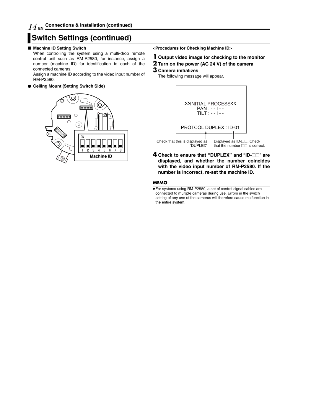
RCeiling Mount (Setting Switch Side)
ON |
|
|
|
|
|
|
|
1 | 2 | 3 | 4 | 5 | 6 | 7 | 8 |
|
| Machine ID |
|
| |||
<Procedures for Checking Machine ID>
1 Output video image for checking to the monitor 2 Turn on the power (AC 24 V) of the camera
3 Camera initializes
The following message will appear.
>>INITIAL PROCESS<<
PAN : - - I - -
TILT : - - I - -
PROTCOL DUPLEX : ID-01
Check that this is displayed as | Displayed as |
“DUPLEX” | that the number LL is correct. |
4 Check to ensure that “DUPLEX” and
MEMO
●For systems using