36 Setting Up the Camera Using RM-P2580 (continued)
EN

 AREA DISPLAY Setup (DIRECTION)
SE |
| SW |
East |
| West |
E |
| W |
|
| |
NE | N | NW |
|
|
MENU button |
|
|
|
|
|
|
| ||
| SET button |
|
|
|
| PAN lever | |||
|
|
|
|
|
|
| |||
|
| CAMERA button |
|
|
| ||||
|
|
|
|
|
| REMOTE CONTROL UNIT | |||
SETUP | CAMERA |
|
| POSITION |
|
|
|
| |
POWER |
|
|
|
|
|
|
| ||
MENU | SET | ALARM |
|
|
| AUTO | |||
|
| KEY LOCK |
|
|
|
|
|
|
|
| LENS |
| CAMERA/POSITION |
|
| PAN/TILT |
| ||
| SPEED | 1 | 2 | 3 | CAMERA | POSI- |
|
|
|
|
|
|
|
|
| TION |
|
|
|
| IRIS |
| 4 | 5 | 6 | 1 | 2 |
CLOSE | OPEN |
|
|
| OPTION | OPTION | |
NEAR | FOCUS | FAR | 7 | 8 | 9 | AUTO | AUTO |
| AF |
| PAN | PATROL | |||
WIDE | ZOOM | TELE | CLEAR | 0 | ENTER |
|
|
|
|
|
| /HOME |
|
|
|
Numeric ENTER
keys button
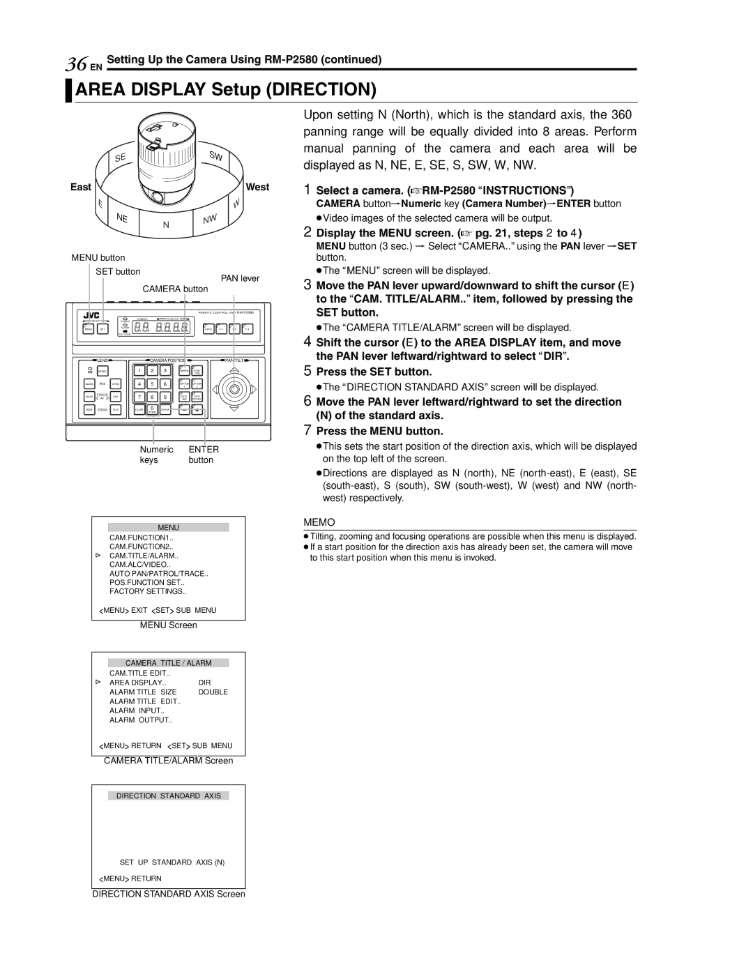
Upon setting N (North), which is the standard axis, the 360° panning range will be equally divided into 8 areas. Perform manual panning of the camera and each area will be displayed as N, NE, E, SE, S, SW, W, NW.
1Select a camera. (ARM-P2580 AINSTRUCTIONSB)
CAMERA buttonNNumeric key (Camera Number)NENTER button
●Video images of the selected camera will be output.
2 Display the MENU screen. (A pg. 21, steps 2 to 4)
MENU button (3 sec.) N Select ACAMERA..B using the PAN lever NSET button.
●The AMENUB screen will be displayed.
3 Move the PAN lever upward/downward to shift the cursor (E) to the ACAM. TITLE/ALARM..B item, followed by pressing the
SET button.
●The ACAMERA TITLE/ALARMB screen will be displayed.
4 Shift the cursor (E) to the AREA DISPLAY item, and move the PAN lever leftward/rightward to select ADIRB.
5 Press the SET button.
●The ADIRECTION STANDARD AXISB screen will be displayed.
6 Move the PAN lever leftward/rightward to set the direction
(N)of the standard axis. 7 Press the MENU button.
●This sets the start position of the direction axis, which will be displayed on the top left of the screen.
●Directions are displayed as N (north), NE
MENU
CAM.FUNCTION1..
CAM.FUNCTION2..
CAM.TITLE/ALARM..
CAM.ALC/VIDEO..
AUTO PAN/PATROL/TRACE..
POS.FUNCTION SET..
FACTORY SETTINGS..
<MENU> EXIT <SET> SUB MENU
MENU Screen
CAMERA TITLE / ALARM
CAM.TITLE EDIT.. |
|
AREA DISPLAY.. | DIR |
ALARM TITLE SIZE | DOUBLE |
ALARM TITLE EDIT.. |
|
ALARM INPUT.. |
|
ALARM OUTPUT.. |
|
<MENU> RETURN <SET> SUB MENU
CAMERA TITLE/ALARM Screen
MEMO
●Tilting, zooming and focusing operations are possible when this menu is displayed.
●If a start position for the direction axis has already been set, the camera will move to this start position when this menu is invoked.
DIRECTION STANDARD AXIS
SET UP STANDARD AXIS (N)
<MENU> RETURN
DIRECTION STANDARD AXIS Screen
