Connections & Installation (continued) | 17 |
EN |
Connection of Alarm Input / Output Terminals Connection of Coaxial Cables
Connect the alarm input/output terminals to external devices such as sensors and buzzers.
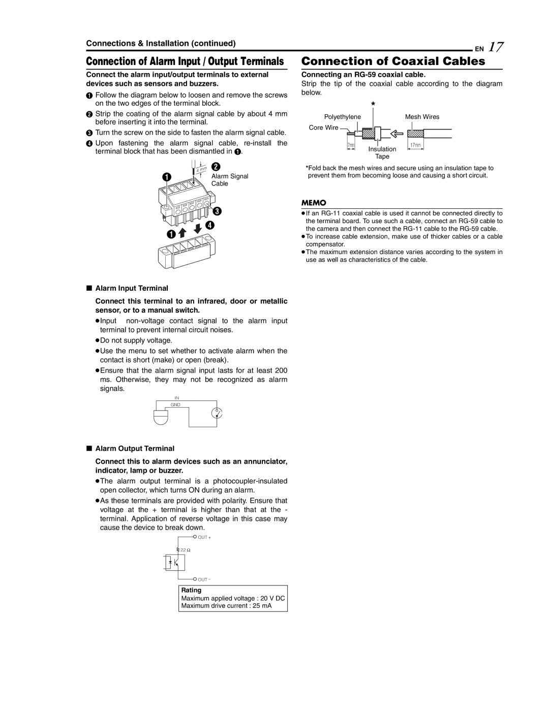
AFollow the diagram below to loosen and remove the screws on the two edges of the terminal block.
BStrip the coating of the alarm signal cable by about 4 mm before inserting it into the terminal.
CTurn the screw on the side to fasten the alarm signal cable.
DUpon fastening the alarm signal cable,
Connecting an RG-59 coaxial cable.
Strip the tip of the coaxial cable according to the diagram below.
| * |
Polyethylene | Mesh Wires |
Core Wire |
|
7mm | 17mm |
| Insulation |
| Tape |
| B |
A | Alarm Signal |
| Cable |
![]()
![]() C
C
D
A ![]()
*Fold back the mesh wires and secure using an insulation tape to prevent them from becoming loose and causing a short circuit.
MEMO
●If an
●To increase cable extension, make use of thicker cables or a cable compensator.
●The maximum extension distance varies according to the system in use as well as characteristics of the cable.
8Alarm Input Terminal
Connect this terminal to an infrared, door or metallic sensor, or to a manual switch.
●Input
●Do not supply voltage.
●Use the menu to set whether to activate alarm when the contact is short (make) or open (break).
●Ensure that the alarm signal input lasts for at least 200 ms. Otherwise, they may not be recognized as alarm
signals.
IN
GND
8Alarm Output Terminal
Connect this to alarm devices such as an annunciator, indicator, lamp or buzzer.
●The alarm output terminal is a
●As these terminals are provided with polarity. Ensure that voltage at the + terminal is higher than that at the - terminal. Application of reverse voltage in this case may cause the device to break down.
![]() OUT +
OUT +
22Ω
![]() OUT −
OUT −