8 Introduction (continued)
EN

 Name and Function of Parts (continued)
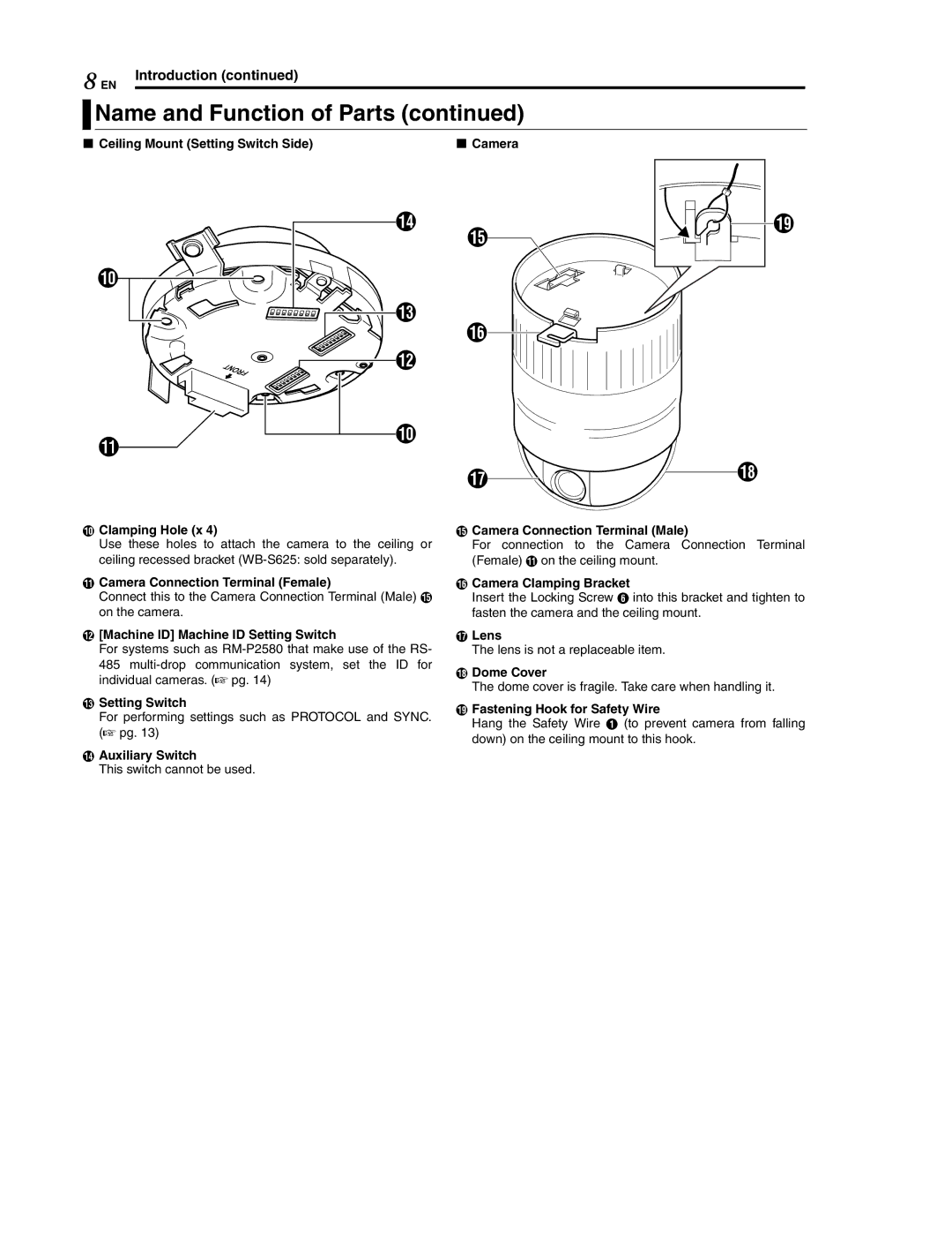
8 Ceiling Mount (Setting Switch Side) | 8 Camera |
J
ONTFR
K
N![]() S O
S O![]()
M![]()
P![]()
![]()
L
J
Q![]()
![]() R
R
JClamping Hole (x 4)
Use these holes to attach the camera to the ceiling or ceiling recessed bracket
KCamera Connection Terminal (Female)
Connect this to the Camera Connection Terminal (Male) O on the camera.
L[Machine ID] Machine ID Setting Switch
For systems such as
MSetting Switch
For performing settings such as PROTOCOL and SYNC. (A pg. 13)
NAuxiliary Switch
This switch cannot be used.
OCamera Connection Terminal (Male)
For connection to the Camera Connection Terminal (Female) K on the ceiling mount.
PCamera Clamping Bracket
Insert the Locking Screw F into this bracket and tighten to fasten the camera and the ceiling mount.
QLens
The lens is not a replaceable item.
RDome Cover
The dome cover is fragile. Take care when handling it.
SFastening Hook for Safety Wire
Hang the Safety Wire A (to prevent camera from falling down) on the ceiling mount to this hook.