English
AV COMPU LINK remote control system
The AV COMPU LINK remote control system allows you to operate JVC’s video components (TV, DVD player*, and VCR) through this receiver.
This receiver is equipped with the AV COMPU
• Refer also to the manuals supplied with your video components.
*“DVD player” on pages 40 and 41 can be replaced with “DVD recorder.”
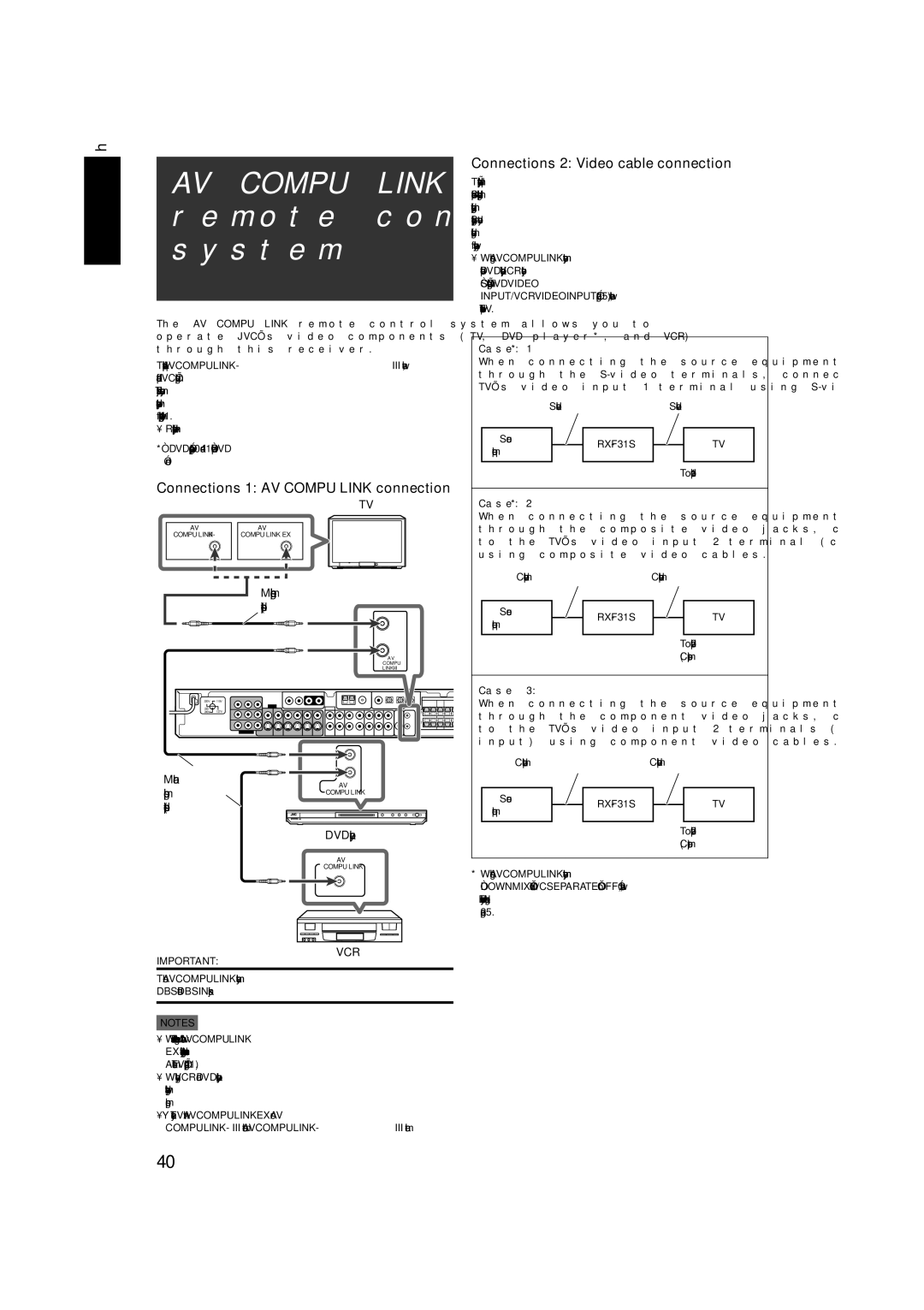
Connections 1: AV COMPU LINK connection
TV
AV |
| AV |
COMPU |
| COMPU LINK EX |
|
|
|
Monaural
AV
COMPU
220V ![]() 110V
110V
230 -
240V 127V
Monaural
AV
DVD player
AV
COMPU LINK
VCR
IMPORTANT:
The AV COMPU LINK remote control system cannot control the DBS tuner connected to the DBS IN jacks.
NOTES
•When connecting the receiver and a TV with the AV COMPU LINK EX terminal by using a component video cable, you cannot use Automatic selection of TV’s input mode (see page 41).
•When connecting only the VCR and DVD player to this receiver, connect it directly to the receiver using cable with the monaural
•You can connect only the TV with AV COMPU LINK EX or AV COMPU
Connections 2: Video cable connection
This receiver is equipped with three types of the video terminals— composite video,
•When using the AV COMPU LINK remote control system, set the video input for the DVD player and the VCR correctly (see “Selecting the component video input
Case 1*:
When connecting the source equipment to the receiver through the
| |||||
|
|
|
|
|
|
Source |
|
|
| TV | |
equipment |
|
|
| ||
|
|
|
|
| |
|
|
|
|
|
|
|
|
|
| To video input 1 | |
Case 2*:
When connecting the source equipment to the receiver through the composite video jacks, connect this receiver to the TV’s video input 2 terminal (composite video input) using composite video cables.
Composite video cable | Composite video cable | |||
|
|
|
|
|
Source |
|
| TV | |
equipment |
|
| ||
|
|
|
| |
|
|
|
|
|
|
|
| To video input 2 | |
|
|
| (Composite) | |
Case 3:
When connecting the source equipment to the receiver through the component video jacks, connect this receiver to the TV’s video input 2 terminals (component video input) using component video cables.
Component video cable | Component video cable | |||||
|
|
|
|
|
|
|
Source |
|
|
| TV |
| |
equipment |
|
|
|
| ||
|
|
|
|
|
| |
|
|
|
|
|
|
|
|
|
|
| To video input 2 | ||
|
|
|
| (Component) | ||
*When using the AV COMPU LINK remote control system, set “DOWN MIX” and “Y/C SEPARATE” to “OFF”; otherwise, this system does not work correctly. For details about each setting, see page 25.
40